
Operation Manual
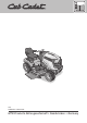


Operating instructions for lawn tractors English
7
t~êåáåÖ
lÄëÉêîÉ=íÜÉ=çêÇ Éê=áå=ïÜáÅ Ü=íÜÉ=
Ä~ííÉêó=áë=ãçìåíÉÇ= ïÜÉå= ÅçååÉÅíáåÖL
ÇáëÅçååÉÅíáåÖ=íÜÉ=íÉêãáå~äëK
Fitting:
First connect the red cable
(+/positive pole) and then the black
cable (–/negative pole).
Removal:
First disconnect the black cable
(–/negative pole) and then the red
cable (+/positive pole).
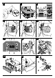
Installing the steering
wheel
Fig. 2c
Connect steering wheel (2)
to steering shaft (1).
Place on top the washer (3) with the
convex side up, and secure the
steering wheel with the screw (4).
Insert cover cap (5, depending
on model).
Operation and Display
elements
=t~êåáåÖK=
a~ã~ÖÉ=íç=íÜÉ=~ééäá~åÅÉK
qÜÉ=Åçåíêçä=~åÇ=áåÇáÅ~íçê=ÑìåÅíáçåë=
ïáää=ÄÉ=ÇÉëÅêáÄÉ Ç=íç=ÄÉÖáå=ïáíÜK=
aç åçí=éÉêÑçêã=~åó=ÑìåÅíáçåë=
~í=íÜáë=ëí~ÖÉ>
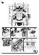
Fig. 1
A Ignition lock with OCR function
B Forward pedal
C Reverse pedal
D Switch for electric cutter deck
lifter *
E Lever for setting the cutting
height *
F Lever for setting height/depth
of the cutter deck * (only in con-
junction with electric cutter deck
lifter)
G Tank contents display
H Lever for the gear release lock
I Dipstick/Filler inlet for gear oil
J Fuel tank/Filler inlet
KStorage bin
L Can holder
M Adjusting lever for seat
N Steering wheel adjusting lever *
O Brake pedal
P Throttle/Choke
Q Switch for parking brake/
Speed control
RChoke
S Display cluster *
T Steering wheel (not illustrated)
U PTO-switch
( * depending on model)
Ignition lock with
OCR function (A)
Fig. 3
This ignition lock features an OCR
function (= user-controlled mowing
in reverse gear).
Start:
Turn the key to the right until
the engine is running, then release.
The key at (normal) allows
mowing in the drive direction.
OCR position:
Turn key to left of normal position
to reverse mowing position
and press the switch (1).
The indicator light (2) comes on and
indicates to the user that the unit
can now mow in reverse and forward
gear.
Stopping:
Turn the key to the left, to .
Note
Do not use the OCR function unless
absolutely necessary, otherwise work
with the key in the normal position.
The OCR function switches off auto-
matically as soon as the key is turned
to the normal position or the engine
is switched off (stop position or dis-
connection of the engine by the safety
interlock system).
Forward pedal (B)
Fig. 1
The pedal controls the speed
in a forward direction.
Reverse pedal (C)
Fig. 1
The pedal controls the speed
in a reverse direction.
Information on forward/
reverse pedal
The further the pedal is pressed
forwards, the faster the unit moves.
To stop or change direction of travel,
release the appropriate pedal.
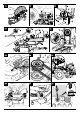
Switch for electric cutter
deck lifter (D)
(depending
on model)
Fig. 4
Is used to lift and lower the cutter
deck (only in conjunction with the
lever for setting the height/depth
of the cutter deck).
Lower cutter deck
= press switch
forwards.
Lift cutter deck
= switch backwards.
Note
The cutter deck is only lowered until
the height, preset with the lever for
setting the height/depth of the cutter
deck, is reached.
Lever for setting the cutting
height (E)
(depending on
model)
Fig. 1
Is used to raise and lower the cutter
deck.
Largest cutting height,
cutters
top = lever to “HI/12”.
Smallest cutting height,
cutters
bottom = lever to “LO/1”.
Lever for setting the height/
depth of the cutter deck (F)
(depending on model)
Fig. 4
Is used to preselect the required
height setting of the cutter deck
(only in conjunction with electric
the cutter deck lifter).
Largest cutting height,
cutters
top = lever to “HI/6”.
Smallest cutting height,
cutters
bottom = lever to “LO/1”.
Note
To adjust the cutter deck, first lift
it all the way using the switch for
the electric cutter deck lifter.