
Operation Manual


7
Depending on the model –
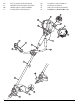
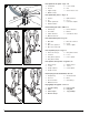
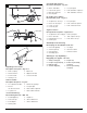
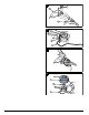
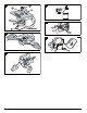
Description of the parts – Figs. 6–8
Selon le modèle –
Description des pièces – Fig. 6–8
Je nach Ausführung –
Beschreibung der Teile – Abb. 6–8
A seconda della versione –
Descrizione delle parti – Fig. 6–8
De acordo com o modelo –
Descrição das peças – Fig. 6–8
Según la versión –
Descripción de las partes – Figuras 6 a 8
Afhankelijk van de uitvoering
Beschrijving van de onderdelen, afb. 6–8
ÁíÜëïãá ìå ôçí ðáñáëëáãÞ –
ÐåñéãñáöÞ ôùí ìåñþí – Åéê. 6–8
1. Shaft coupling 5. Main hole
2. Release button 6. Upper shaft tube
3. Screw handle 7. Lower shaft tube
4. Guide groove
1. Accouplement d'arbre 4. Rainure de guidage
2. Bouton 5. Trou principal
de déclenchement 6. Tube d'arbre supérieur
3. Poignée à vis 7. Tube d'arbre inférieur
1. Schaftkupplung 5. Hauptloch
2. Auslöseknopf 6. oberes Wellenrohr
3. Schraubgriff 7. unteres Wellenrohr
4. Führungsrille
6
1 2
3
4
1
5
6
2
7
7
3
8
1. Giunto dell’albero 5. Foro principale
2. Pulsante di sgancio 6. Tubo dell'albero superiore
3. Manopola della vite 7. Tubo dell'albero inferiore
4. Gola di guida
1. Acoplamento da lança 5. Furo principal
2. Botão de desengate 6. Tubo ondulado superior
3. Punho roscado 7. Tubo ondulado inferior
4. Fenda de guia
1. Acoplamiento de la espiga5. Orificio principal
2. Botón de traba 6. Tubo superior del eje
3. Empuñadura a rosca 7. Tubo inferior de eje
4. Ranura guía
1. Schachtkoppeling 5. Hoofdgat
2. Activeringsknop 6. Bovenste asbuis
3. Schroefgreep 7. Onderste asbuis
4. Geleidingsgroef
1. Æåýîç óôåëÝ÷ïõò 5. Êýñéá ïðÞ
2. Êïõìðß åíåñãïðïßçóçò 6. ÅðÜíù êõìáôïåéäÞò
3. ÂéäùôÞ ëáâÞ óùëÞíáò
4. ÁõëÜêé ïäÞãçóçò 7. ÊÜôù êõìáôïåéäÞò
óùëÞíáò