
User Manual


2 310-2200 EZT
®
pump and thus reverses the direction of the mo-
tor output rotation. The pump and motor are of
the axial piston design and utilize spherical nosed
pistons which are held against a thrust race by
internal compression springs.
The 310-2200 has a self contained fluid supply
and an internal filter. The fluid is forced through
the filter by a positive “head” on the fluid in the
housing/expansion tank with an assist by the
negative pressure created in the pump pistons
as they operate.
The check valves in the center section are used
to control the make-up flow of the fluid to the
low pressure side of the loop.
A cam style, block lifting bypass is utilized in the
310-2200 to permit moving the vehicle for a short
distance at a maximum of 2 m.p.h. (3.2 Km/h)
without starting the engine.
WARNING
Actuating the bypass will result in the loss
of hydrostatic braking capacity. The
machine must be stationary on a level
surface and in neutral when actuating the
bypass.
INTRODUCTION
The purpose of this manual is to provide infor-
mation useful in servicing the Hydro-Gear
®
Inte-
grated Zero-Turn Transaxle (EZT
®
). This manual
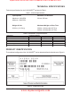
includes the EZT’s general descriptions, hy-
draulic schematics, technical specifications, ser-
vicing and troubleshooting procedures.
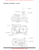
The transaxle normally will not require servicing
during the life of the vehicle in which it is in-
stalled. Should other servicing be required, the
exterior of the transaxle will need to be thor-
oughly cleaned before beginning most proce-
dures. Do not wash the transaxle while it is hot.
Do not use a pressure washer to clean the unit.
GENERAL DESCRIPTION
The 310-2200 is a self contained unit designed
for the transfer and control of power. It provides
an infinitely variable speed range between zero
and maximum in both forward and reverse
modes of operation.
This transaxle uses a variable displacement
pump with a maximum displacement of 10cc per
revolution, and motor with a fixed displacement
of 10cc per revolution. The variable displace-
ment pump features a trunnion mounted
swashplate with a direct-proportional displace-
ment control. Reversing the direction of the
swashplate reverses the flow of oil from the
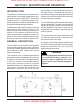
SECTION 1. DESCRIPTION AND OPERATION
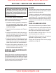
Figure 1. Hydraulic Schematic
www.mymowerparts.com
Hydro Gear Parts or New Units Call 606-678-9623 or 606-561-4983