
User Manual
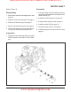


310-2200 EZT
®
21
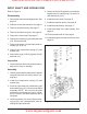
Refer to Figures 12-21.
Disassembly
1. Remove the bypass arm and control arm. See
page 15.
2. Drain the oil from the transaxle. See page 9.
3. Remove the side housing. See page 17.
4. Remove the reduction gears. See page 18.
5. Remove the motor shaft. See page 19.
6. Remove the input shaft and bypass rod. See
page 20.
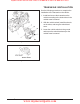
7. (See Figure 12) Remove the swashplate
(19) and pump cylinder block (4) as one as-
sembly. NOTE: Removal will be aided by ap-
plying a small amount of pressure on the trun-
nion mounted swashplate towards the cen-
ter section. Also note that the control arm (23,
page 28) may be loosely assembled at this
point to assist in swashplate removal. While
gently removing the swashplate and block
assembly, keep the block face flush with the
center section to minimize damage to the
running surface.
8. (See Figure 13) Disassemble the pump cyl-
inder block (4) from the swashplate (19).
9. (See Figure 14) Check each piston for
proper operation by pressing the pistons in
and releasing them in the block bore. Disas-
semble the pump cylinder block. Check for
piston/block wear in the cylinder bore. Inspect
the pistons (A), piston springs (C) and thrust
washers (B) for excessive wear or damage.
NOTE: Thrust washers may be held in place
in the piston by residual oil.
10.Reassemble the pistons, springs and wash-
ers into the cylinder block and set aside.
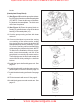
11. (See Figure 15) Remove the thrust bearing
assembly (35) from the swashplate (19).
(Center Section/Filter)
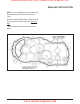
12.(See Figure 16) Remove the center section
mounting screws (12). NOTE: The center
section is under motor block piston spring
pressure. These screws are factory installed
to 700 lb-in (80 Nm) and use an anaerobic
thread adhesive. A breaker bar will be re-
quired at this step. Clean the internal threads
of the mounting holes with compressed air.
13.Remove the center section and filter assem-
bly (57, Figure 17). NOTE: Bypass plate (Fig-
ure 17) may slide out of the center section.
14.Remove the filter cover by pressing in and
down on the filter cover tabs. Discard the
cover.
15.Note the location of both check plugs (56)
before removal for correct replacement dur-
ing reassembly. Remove and inspect the
check plug assemblies (56) for debris or
damage.
16.Remove the filter base (61) and discard it.
NOTE: The filter base is included in the filter
kit to be installed during reassembly of the
unit.
(Motor Block)
17.(See Figure 19) Remove the motor cylinder
block assembly (4) from the housing (1).
18.Disassemble the motor cylinder block as-
sembly (4). Check each piston for proper
operation by pressing the pistons in and re-
leasing them in the block bore. Disassemble
the motor cylinder block. Check for piston/
block wear in the cylinder bore. Inspect the
pistons, piston springs and thrust washers
for excessive wear or damage. NOTE:
Thrust washers may be held in place in the
piston by residual oil.
19.Reassemble the pistons, springs and thrust
washers into the cylinder block and set aside.
HYDRAULIC COMPONENTS
www.mymowerparts.com
Hydro Gear Parts or New Units Call 606-678-9623 or 606-561-4983