
User Manual


20 310-2200 EZT
®
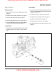
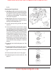
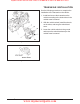
Figure 11. Input Shaft and Bypass Rod Assembly
Refer to Figure 11.
Disassembly
1. Remove the control arm and bypass arm. See
page 15.
2. Drain the oil from the transaxle. See page 9.
3. Remove the side housing. See page 17.
4. Remove the reduction gears. See page 18.
5. Remove the motor shaft. See page 17.
6. Remove the retaining ring (34) and shaft seal
(33). Discard the seal.
7. Remove the spacer (32) and input shaft as-
sembly (29, 30 & 31).
8. Remove the compression spring (27) and
washer (28).
9. Remove the rings (14 & 16), bypass rod (15)
and seal (13).
Inspection
1. Inspect the input shaft components and by-
pass rod for wear or damage.
Assembly
1. Visually ensure that the pump block is aligned
concentrically with the center section run-
ning face.
2. Install the compression spring (27) and
washer (28).
3. Insert the input shaft (29), with bearing (30)
and retaining ring (31), into the pump block
assembly. NOTE: Do not force the shaft
and bearing as damage may occur. If align-
ment is correct, the shaft assembly will fit
into place.
4. Install the washer (32), seal (33) and retain-
ing ring (34). Use a seal protector when in-
stalling the input shaft seal.
5. Deburr the end of the bypass rod. Install the
bypass rod (15), retaining ring (14), seal (13)
and retaining ring (16).
6. Install the motor shaft. See page 19.
7. Install the reduction gears. See page 18.
8. Install the side housing. See page 17.
9. Install new seals in the side housing. See
page 16.
10.Fill the transaxle with oil. See page 9.
11. Install the bypass arm and control arm. See
page 15.
INPUT SHAFT AND BYPASS ROD
www.mymowerparts.com
Hydro Gear Parts or New Units Call 606-678-9623 or 606-561-4983