
User Manual


310-2200 EZT
®
17
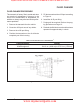
Refer to Figure 8.
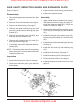
Disassembly
1. Remove the control arm and bypass arm. See
page 15.
2. Remove the oil from the transaxle. See page
9.
3. Remove the brake arm assembly (55), re-
taining ring (14) and cog brake disc (100).
4. Remove the lip seal (10).
5. Remove the housing screws (9).
6. Pull the side housing (2), leaving the axle
(49) and bull gear (46) assembled in the main
housing. It may be necessary to use screw-
drivers at the pry points to break loose the
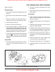
sealant (positions H-L and M-P, Figure 8).
7. Clean off
all the old sealant on the side and
main housings. Take care not to damage the
sealing surfaces. A wire brush and solvent is
effective.
Inspection
1. Check the brake arm brake disc for exces-
sive wear or teeth damage. Replace if nec-
essary.
Figure 8. Cog Brake and Side Housing Assembly
2. Check for excessive looseness at the arm
pivot point.
3. Inspect the bearing and bushing areas in the
side housing.
Assembly
1. Apply a bead of sealant around the perim-
eter of the side housing face. See sealant
pattern on page 27.
2. Install the locating pins (8), if not already in-
stalled.
3. Install the side housing (2). Use care not to
smear the sealant bead.
4. Install the side housing screws (9). Refer to
the screw tightening pattern in Figure 8 and
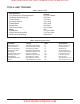
torque specification in Table 6 on page 14.
5. Install the remaining seals. Refer to page 16.
Remember to use a seal protector during in-
stallation.
6. Install the brake disc (100), retaining ring
(14) and brake arm assembly (55).
7. Fill the transaxle with new oil. See page 9.
8. Install the bypass arm and control arm. See
page 15.
COG BRAKE AND SIDE HOUSING
www.mymowerparts.com
Hydro Gear Parts or New Units Call 606-678-9623 or 606-561-4983