
User Manual


16 310-2200 EZT
®
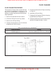
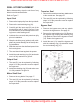
Figure 7. Seal Kit Replacement
Before disassembly, wipe the unit free of any
debris to avoid contamination.
Refer to Figure 7.
Input Seal
1. Remove the input pulley from the input shaft.
2. Remove the seal retaining ring (34).
3. Carefully pull the input seal (33) out of the
housing bore with a “hook” type tool. Care
must be taken to avoid damage to the hous-
ing bore or shaft sealing area.
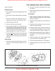
4. Lubricate the new seal with petroleum jelly
prior to installation.
5. Wrap the shaft keyway (splines) with cello-
phane to prevent damage to the seal lip dur-
ing installation.
6. Slide the seal over the shaft and press it into
the housing bore.
7. The seal should seat against the spacer.
8. Install the seal retaining ring (34) and make
sure it is fully seated in its groove.
Output Seal
1. The seal (51) can be replaced by following
steps 2-6 of the procedure used to replace
the input seal.
2. Install the retaining ring (34) and make sure
it is fully seated in its groove.
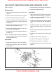
Motor Shaft Seal
1. Remove the cog brake. See page 17.
2. The seal (10) can be replaced by following
steps 3-6 of the procedure used to replace
the input shaft.
Trunnion Seal
1. Remove the control arm and any attachments
to the control arm. See page 15.
2. The seal (20) can be replaced by following
steps 3-6 of the procedure used to replace
the input shaft.
Bypass Seal
1. Remove the bypass arm and any attach-
ments to the bypass arm. See page 15.
2. Remove the seal retaining ring (16). Remove
the bypass rod, keeping the retaining ring
(14) attached. Remove the bypass rod seal
(13). Deburr the bypass rod.
3. Install the seal (13). Install the bypass rod
with the retaining ring (14) attached. Install
the seal retaining ring (16).
SEAL KIT REPLACEMENT
www.mymowerparts.com
Hydro Gear Parts or New Units Call 606-678-9623 or 606-561-4983