
User Manual


310-2200 EZT
®
15
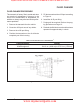
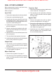
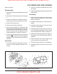
Figure 6. Control Arm and Bypass Arm
Refer to Figure 6.
Disassembly
1. Loosen and remove the lock nut (26) and flat
washer (24). Discard the lock nut (26) and
flat washer (24).
2. Remove the torx head screw (25) from the
directional control.
3. Remove control arm (23) and pucks (22).
Discard the pucks.
4. Remove the bypass arm retaining ring (18)
and bypass arm (17). Discard the retaining
ring.
5. If necessary, remove and replace the con-
trol arm stop stud (21).
Inspection
1. Inspect the control arm stop stud (21) for
wear or damage.
2. Inspect the control arm (23) for wear or dam-
age.
3. Inspect the bypass arm (17) for wear or dam-
age.
Assembly
1. Install the bypass arm (17) onto the bypass
rod. Secure the bypass arm with a new re-
taining ring (18).
2. Replace the control arm stop stud (21) if
removed. Torque according to specifications
in Table 6 on page 14.
3. Install the control arm (23).
4. Install the control arm screw (25). Refer to
Table 6 for screw torque specifications.
CONTROL ARM AND BYPASS ARM
www.mymowerparts.com
Hydro Gear Parts or New Units Call 606-678-9623 or 606-561-4983