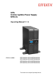
UPS Uninterruptible Power Supply MTD-XL Operating Manual V. 1.
UPS MTD-XL Legal notice Legal notice by EFFEKTA Regeltechnik GmbH EFFEKTA Regeltechnik GmbH, 78628 Rottweil, retains the copyright to this documentation. This documentation is solely intended for the operator and his staff. The content of this documentation (texts, figures, drawings, graphics, plans, etc.) may not be copied or distributed in part or in full without our consent in writing, nor can it be used without authorisation for competitive purposes or given or made accessible to third parties.
UPS MTD-XL Table of Contents Table of Contents 1. Introduction ............................................................................................................... 5 1.1 Introduction ............................................................................................................... 5 1.2 Validity ...................................................................................................................... 6 1.3 Storage .................................................
UPS MTD-XL Table of Contents 9. Troubleshooting ...................................................................................................... 65 10. Software ................................................................................................................. 67 11. Maintenance and Service ...................................................................................... 68 11.1 Measuring the backup-time (support time) ........................................................
UPS MTD-XL Introduction 1. Introduction 1.1 Introduction Dear Operator, You are about to operate an uninterruptible power supply. This operating manual should provide you with support for working responsibly and basic information about the uninterruptible power supply, namely how it operates, its application and what you should do in the event of malfunctioning.
UPS MTD-XL 1.2 Introduction Validity The descriptions in this operating manual relate solely to the uninterruptible power supply defined in the technical data as a whole or as it refers to modules, components and individual parts that were developed and built by EFFEKTA Regeltechnik GmbH. 12. Technical Data 1.3 Storage This operating manual for the device must be stored in the vicinity of the device at all times so it is immediately available if need be. 1.
UPS MTD-XL MTD series Introduction 7
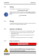
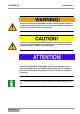
UPS MTD-XL Introduction Text that is marked with WARNING! provides a warning about hazards. If accident prevention measures are not taken, these hazards may result in serious (irreversible) injuries or even death! Text that is marked with CAUTION! provides a warning about hazards. If accident prevention measures are not taken, these dangerous situations can lead to slight or medium reversible injuries.
UPS MTD-XL Introduction 1.4.2 Warning information 1.4.2.1 Warning about danger spots General warning about danger spots! 1.4.2.2 Specific warning Warning about dangerous electrical voltage! Warning about proper handling of accumulators! 1.4.
UPS MTD-XL 1.4.4 Introduction General symbols ● This dot marks descriptions of activities that you should carry out. – This dash marks specification lists. This arrow marks a cross reference. If a cross reference to another chapter is necessary in the text, this is shortened for clarity. Example: OM, 2 Safety Instructions This means: See Operating Manual, Chapter 2 Safety Instructions.
UPS MTD-XL 1.5 Introduction Information Obligation This operating manual must be read, understood and all its points must be taken note of by all persons that are responsible for the – Operation – Cleaning and – Disposal of this device. EFFEKTA Regeltechnik GmbH is not liable for damage incurred or caused by staff who have not been trained or who have been insufficiently trained! 1.
UPS MTD-XL Introduction – In the event that the product is incompatible due to possible technical innovations or regulations that occur after the purchase. – In the event of incompatibility or malfunctioning that was caused by product components we did not install. – In the event of developments that are related to the normal ageing process of the product (wear parts). – In the event of defects that were caused by external fixtures.
UPS MTD-XL 1.6.1 Introduction Limitation of liability Claims to damage compensation are excluded unless they involve intent or gross negligence by EFFEKTA Regeltechnik GmbH or its employees. This does not affect liability according to the Product Liability Act. Under no circumstances are we liable for: – Claims that third parties make against you due to losses or damage. – Loss or damage of your records or data or the costs of recovering this data.
UPS MTD-XL 1.8 Introduction Positioning Do not install in an area in which combustible vapours arise e.g. from petrol tanks, engine compartments, etc. The UPS is designed for operation in ventilated rooms with an ambient temperature of 0° to 40°C. If the UPS is exposed to severe and quick temperature changes, there is danger of condensation. Before you take additional steps, an acclimatization period of at least 2 hours is to be observed. Never place or operate the device in a moist environment.
UPS MTD-XL Safety Instructions 2. Safety Instructions 2.1 Introduction The UPS is a device that has been produced according to the rules and regulations of technology for an uninterruptible power supply. The device and related components, modules and units comply as a whole, as well as in individual parts, with the legal safety standards and conform with the EC-Machinery Directive 2006/42/EG.
UPS MTD-XL 2.3 2.4 Safety Instructions Avoiding Personal Injury / Property Damage Please read this operating manual carefully to familiarise yourself with the device. In particular, take note of the information regarding the installation and commissioning of the device. Only operate the product in an appropriate and proper way and within the parameters stated in the technical data. Only perform maintenance and service work that is described in the documentation.
UPS MTD-XL 2.5 Safety Instructions Connection The UPS may only be connected to a grounded isolated ground receptacle or if connected via terminals, the protective earth conductor must be connected without fail. The device may not be used without the PE under any circumstances. The socket for the domestic installation must be easily accessible and in proximity to the UPS. Keep the cable length as short as possible in the case of permanent wiring.
UPS MTD-XL 2.6 Safety Instructions Operation Before the appliances are connected to the outlet, the basic configuration must be completed. Especially the output voltage is of high importance regarding the appliances. The UPS-system contains an energy storage (accumulators). This means that the outlet can be current-carrying even when the UPS is not connected to the mains input terminal.
UPS MTD-XL Safety Instructions Defective accumulators have to be disposed of in an environmentally compatible manner. Never dispose of accumulators with regular household waste. Local disposal regulations must be observed. 2.8 Maintenance, Service and Malfunctions Attention – Danger of electric shocks. Even after switching off the supply with the power button or after disconnecting the accumulator feed respectively, parts of the UPS can still carry high voltages.
UPS MTD-XL Safety Instructions – Wear personal protective equipment (safety glasses, gloves, face shield, etc.); – The UPS may not be disassembled.
UPS MTD-XL 3. UPS Device Description UPS Device Description This manual shall provide basic information about one-phase line-interactive UPS-systems, like the mode of operation, utilization of the different functions and what to do in case of malfunctions. In addition, this manual contains instructions for the proper transportation and storage, as well as for the handling and installation of the UPS-equipment. The planning guidelines in this manual refer only to the specific requirements of UPS-systems.
UPS MTD-XL UPS Device Description The uninterruptible power supply units of the MTD-XL series to not have internal accumulators. These are available as separate units. Depending on the field of application, accumulator modules of up to a total power of maximum 100 AH can be connected to the device. Please see the technical specifications for details ( 12 Technical Data). 1 2 Unit Accumulator module Fig.
UPS MTD-XL 3.1 UPS Device Description Elements on the front of the device On the front side of the device are all operating and display elements necessary for the normal operation of the UPS. 1 5 4 3 2 1 2 3 4 5 LCD-display "Enter" button "Select" button "Alarm" button "ON/ OFF"-button Fig.
UPS MTD-XL 3.1.1 UPS Device Description LCD-display The LCD-Display shows the operating mode and a variety of status values. The following views can be selected with the help of the up and down buttons: Display MTD series Description Function Input frequency and voltage Shows the input frequency and voltage. Display input connector Lights up when the input voltage is faultless. Output frequency and voltage Shows the output frequency and voltage.
UPS MTD-XL MTD series UPS Device Description LCD-Display-Text Description STbY The UPS is in standby mode. IPVL The input voltage is too low. IPVH The input voltage is too high. IPFL The input frequency is too low. IPFH The input frequency is too high. NORM The UPS operates in line mode. AVR The UPS operates in AVR mode. bATT The UPS operates in battery mode. TEST The UPS is in battery test / function mode. OPVH The output in battery mode is too high.
UPS MTD-XL 3.1.2 UPS Device Description Button ON / OFF button Please push the button for more than 3 seconds to turn the UPS on or off. To end the fault mode of the UPS, you have to disconnect the UPS from the input voltage and keep the ON / OFF button pressed for at least two seconds to turn off the UPS. UPS test / turning off an alarm To perform a basic functions test, keep the button pressed for at least 3 seconds. To perform a battery test, keep the button pressed for at least 10 seconds.
UPS MTD-XL 3.2 UPS Device Description Elements on the back of the device 1 2 3 4 5 6 7 8 UPS output 10A Input overvoltage protection (RJ 45) Output overvoltage protection (RJ 45) Communication interface Mains-input "EPO"-port USB-port RS232-port Fig.
UPS MTD-XL UPS Device Description 1 2 3 4 5 6 7 8 UPS output 10A Input overvoltage protection (RJ 45) Output overvoltage protection (RJ 45) Communication interface Mains-input "EPO"-port USB-port RS232-port Fig. 3-2 - 1 1 2 3 4 5 6 7 8 9 UPS output 10A Input overvoltage protection (RJ 45) Output overvoltage protection (RJ 45) Communication interface Mains-input "EPO"-port USB-port RS232-port UPS output 16A Fig.
UPS MTD-XL UPS Device Description The plug-in connectors "UPS-Output" and "Mains-Input" are on mains potential when connected. However, there can still be a dangerously high voltage on the plug-in connectors even while disconnected, due to device-internally loaded capacities. As soon as mains input voltage is present, the loading unit is automatically activated. I.e. the internal battery bank is already being charged, even though the UPS has not been switched on. 3.2.
UPS MTD-XL 3.2.3 UPS Device Description Communication interface After unscrewing the cover, various additional expansion cards can be installed, e.g. a relay card. Fig.
UPS MTD-XL UPS Device Description Fig.
UPS MTD-XL UPS Device Description Fig.
UPS MTD-XL 3.2.4 UPS Device Description Mains Input IEC connector socket 10 A for MTD-XL 1000 and 1500. IEC connector socket 16 A for MTD-XL 2000 and 3000. Mains power supply connection with enclosed supply cable with two-pin earthed plug. The protective earth conductor must be connected! Please always note the specified input voltage on the identification tag or in the technical specifications in this operating manual respectively. 3.2.
UPS MTD-XL UPS Device Description The shut-down signal must remain active for at least 20 ms, to ensure proper operation. 3.2.6 USB-port The USB-port serves to connect the UPS to a PC. 3.2.7 RS232-port The RS232-port serves to connect the UPS with a PC. 3.2.8 Input and output overvoltage protection Overvoltage protection for phone, fax or modem.
UPS MTD-XL 3.3 UPS Device Description Device Modification The UPS can be set up in different ways: – vertical as a tower device on supporting feet – horizontal mounting in a 19" rack. Depending on the way of positioning, the LCD-Display has to be rotated and the assembly brackets have to be mounted for the 19"-slot. 3.3.1 Setting up the UPS as a tower device Fig. 3-3 - 1 Tower device The following steps have to be taken: Rotate the display to a vertical position.
UPS MTD-XL UPS Device Description Procedure for the rotation of the display: 12 1 2 Snap lock Display Fig. 3-3 - 2 Rotate display Press the snap lock (1). Pull the control panel (1) carefully forward and from the housing. Rotate the display 90°, so that it fits properly for a horizontal set-up. Push the display into the housing until it snaps into place. The display is connected through a flat ribbon cable. Do not pull the cable.
UPS MTD-XL UPS Device Description Attention – Danger of electric shocks. Perform this task only while the UPS is deengergized. Even after switching off the supply with the power button or after disconnecting the accumulator feed respectively, parts of the UPS can still carry high voltages. Fig.
UPS MTD-XL UPS Device Description Fig. 3-3 - 4 MTD series Setting up the UPS Mount the UPS on the supporting feet.
UPS MTD-XL 3.3.2 UPS Device Description Setting-up the UPS as a rack-mounted device Fig. 3-3 - 5 Rack-mounted device The following steps have to be taken: MTD series Rotate the display to a horizontal position. Fit the mounting brackets. Mount the UPS in the slot of the 19" rack.
UPS MTD-XL UPS Device Description Procedure for the rotation of the display: 1 1 2 Snap lock Display Fig. 3-3 - 2 2 Rotate display Press the snap lock (1). Pull the control panel (1) carefully forward and from the housing. Rotate the display 90°, so that it fits properly for a horizontal set-up. Push the display into the housing until it snaps into place. The display is connected through a flat ribbon cable. Do not pull the cable.
UPS MTD-XL MTD series UPS Device Description 41
UPS MTD-XL UPS Device Description Fig. 3-3 7 Fit the two mounting brackets to the sides of the housing. Fig. 3-3 - 8 MTD series Mounting bracket 19" rack Slide the UPS into the slot of the 19" rack.
UPS MTD-XL UPS Device Description 1 1 Screws Fig. 3-3 - 9 MTD series Mounting of the UPS in a 19" rack.
UPS MTD-XL 3.4 UPS Device Description Connection of the Accumulator Modules The connection of the accumulator modules may only be performed by a trained electrician who is familiar with the product and the inherent hazards. The accumulator modules may only be connected while the units are switched off. Before connecting the accumulator modules, make sure that no appliances are connected to the UPS. Even when switched-off, the UPS and the accumulator modules can carry high voltages.
UPS MTD-XL UPS Device Description The display is connected through a flat ribbon cable. Do not pull the cable.
UPS MTD-XL UPS Device Description 1 Screws Fig. 3-4 - 2 Remove the fastening screws (1). 1 Connection cable Fig. 3-4 – 3 MTD series Fastening screws front panel Front panel Carefully fold down the front panel. Connect the connection cable (1) of the UPS with the accumulator module. Colour-coding and form prevent that the plugs could be connected the wrong way.
UPS MTD-XL UPS Device Description 1 2 Front panel Cable feedthrough Fig. 3-4 - 4 MTD series Front panel - Cable feedthrough At the front panel (1) of the UPS, as well as of the accumulator module you find cable feedthroughs (2) that are closed in the initial state, as delivered. Carefully break the plastic parts of the cable feedthroughs (2) open with pliers and remove it from the front panel. Make sure there are no sharp edges that could damage the cables.
UPS MTD-XL UPS Device Description Fig. 3-4 - 5 MTD series Connection of the accumulator module After the connection of the accumulator module, reassemble the front panel and display on the UPS and the accumulator module in reverse order.
UPS MTD-XL UPS Device Description 1 2 1 2 Protective earth connection Protective earth cable Fig. 3-4 - 6 MTD series Earthing Connect the protective earth ports (1) of the UPS and the accumulator module with a protective earth cable (2) (at least 1.5 mm2).
UPS MTD-XL Storage and Unpacking 4. Storage and Unpacking 4.1 Storage of the UPS In case the device is not being installed immediately, please note the following: Always store the device and any accessories in their original packaging. The suggested ambiance temperature for the storage is between: + 0 °C ... + 40 °C. Protect the device and packaging from moisture and liquids.
UPS MTD-XL 5. System Description System Description The UPS provides an uninterruptible one-phase voltage for operations critical appliances. In addition to providing power to the appliance, it also maintains the internal accumulators in charged condition. In the case of a mains failure or interference (e.g. due to voltage fluctuation), the UPS continues to provide a clean supply voltage from the UPS-output without interruption. During the backup mode, power is provided from the battery bank.
UPS MTD-XL System Description If a mains failure continues beyond the backup time of the UPS, the UPS shuts down to avoid a total discharge of the accumulators. As soon as the mains power supply returns, the UPS automatically turns on again, supplies electricity to the appliance and controls the charging of the battery bank. Prominent performance features of the MTD series are: – Short switching period to backup mode in the event of a failure of the primary power supply.
UPS MTD-XL 6. UPS Installation and Connection UPS Installation and Connection All requirements listed in the technical specifications concerning ambient and operating conditions must be met, to ensure proper operation of the UPS. Please note the following during set-up / installation of the UPS: 6.1 Avoid extreme temperatures and humidity. Ensure proper horizontal set-up. Allow adequate space for ventilation of the device. Ensure a proper flow channel. Pay attention to the system layout.
UPS MTD-XL UPS Installation and Connection The appliances will continue to be supplied with power for the duration of the backup time.
UPS MTD-XL UPS Installation and Connection 1 2 3 4 5 Mains power supply 10 A (for type 1000 / 1500) 16 A (for type 2000 / 3000) 0,75 mm2(for type 1000 / 1500) 1,5mm² (for type 2000 / 3000) Load 1 Load 2 Fig. 6-1 - 1 Connection of UPS and appliances MTD series 1000 / 1500 S: 1: 6.2 2000 / 3000 10 A 0,75 mm 16 A 2 1,5 mm² UPS communication port The UPS is equipped with a convenient communication interface to facilitate the exchange of data with the UPS.
UPS MTD-XL 6.2.1 UPS Installation and Connection RS232 communication port Only use the connection cable (1 : 1) that is listed in chapter "Accessories" for the connection. Pin Configuration 2 RS232 Receiving line Rx or shut down SD 3 RS232 Sending line Tx 5 RS232 PE The communication port is electrically absolutely isolated. The UPS can also be forced into immediate shut-down during backup mode via the RS232 interface.
UPS MTD-XL 6.3 6.3.1 UPS Installation and Connection Connection sequence Connect the accumulator module with the UPS. Connect the UPS with the mains power supply; both, the mains and the UPS must be safely switched-off during this process. Before the appliances are connected to the outlet, the basic configuration must be completed. Connect the appliance/s with the UPS. Make sure that all appliances are switched-off.
UPS MTD-XL Operation 7. Operation 7.1 Operation of the UPS The operator of the UPS-system must always adhere to the instructions in this operating manual. The operator may only carry out the following measures and must always exercise particular care: Use of the operating controls: switching-on, starting and switchingoff the UPS. Reading of the display messages and interpretation of the acoustic warning signals. Triggering the test mode.
UPS MTD-XL Operation Selection mode: In selection mode the UPS operates with input voltages between - 30 % and appr. + 20%. Battery mode: The UPS announces the battery mode by an acoustic signal in 4 seconds intervals. The display shows the message "bATT". If the load capacity of the batteries falls, an acoustic signal sounds every second and the display shows the message "bATL". Standby mode: The UPS is in standby mode when it is turned off and connected to the mains power supply and appliances.
UPS MTD-XL Operation Menu Description Function Values OPV Output voltage Setting the output voltage [220] = 220 V [230] = 230 V [240] = 240 V AVR Operating mode Setting the operating mode [000] = normal operating mode [001] = selection mode [002] = generator mode EbM External battery module Details on the number of external battery modules 0 - 9 = Number of external battery modules TEST Self-test [000] = deactivated [001] = activated AR Automatic reboot GF ECO – MODE UPS self-test a
UPS MTD-XL 7.1.4 Operation Configuration of the UPS outputs The UPS outputs are divided into two segment groups (LS1 and LS2). 1 2 UPS output LS1 UPS output LS2 Fig. 7-1 - 1 Segment groups - UPS output You can activate or deactivate these segment groups individually. To configure the segment groups, follow these steps: Press the "Enter" button for 3 seconds. The UPS switches into settings mode. Select either "LS1" or "LS2" with the "Select" button. Press the "Enter" button for one second.
UPS MTD-XL 7.1.5 Operation Configuration of the external battery module Before you can commission the UPS you have to configure the number of external battery modules. To set the number of external battery modules, follow these steps: Press the "Enter" button for 3 seconds. The UPS switches into settings mode. Use the "Select" button to select the value "EBM". Press the "Enter" button for one second. The setpoint starts blinking.
UPS MTD-XL 7.1.7 Operation Communication For the exchange of data between the UPS and a superior system, the respective software packages are required. Please see chapter "Software" for the range of services.
UPS MTD-XL 8. Commissioning of the UPS-System Commissioning of the UPS-System To ensure proper fault-free commissioning, these steps have to be followed: MTD series Connect the external battery module with the UPS. Connect the UPS with the enclosed connection cable to the mains power supply. Adjust the necessary settings on the UPS, like e.g. activation of outputs. Connect the appliances with the UPS-outputs and switch to normal operating mode.
UPS MTD-XL 9. Troubleshooting Troubleshooting Only authorized trained personnel may perform troubleshooting tasks on the UPS. Fault Cause Measures Alarm signal in 4 seconds intervals The UPS is in battery mode. Check the mains power supply input. Alarm signal every second and the message "bATL" appears on the display. The battery voltage is too low. Save all data of the appliances and switch these of. Charge the battery for 24 hours.
UPS MTD-XL Troubleshooting If the fault indicator you registered cannot be found in this table, please contact out service centre and provide the following information: 1. Model number, serial number. 2. Date on which the issue occurred. 3. Detailed description of the problem.
UPS MTD-XL 10. Software Software With a suitable software package the configurations and operating statuses of the UPS can be determined and processed via the communication interface. The software packages are available from the manufacturer / dealer or through the service hotline. Through these channels you can receive useful information about the suitable software packages for your UPS to fit your needs. See also our website: http://www.effekta.
UPS MTD-XL 11. Maintenance and Service Maintenance and Service You may expect a long service life and interference-free operation of your UPS at a minimum of maintenance effort. However, the reliability of the UPS is greatly dependant on the ambient conditions. The ambient temperature and humidity must remain within the given range. In addition, the area around the UPS should be kept clean and free of dust.
UPS MTD-XL Maintenance and Service Remember that after the measuring the accumulators of the system will be discharged. I.e. the UPS-system must operate in line mode or charging mode respectively for several hours (min. 5 h), before it will again be operational at about 80% capacity.
UPS MTD-XL 11.3 Maintenance and Service Service-Log Please always enter all maintenance and service work conducted on the UPS into the service-log.
UPS MTD-XL 11.4 Maintenance and Service Service-Hotline If unexpected problems occur with the photovoltaic solar inverter or you need safety information, please contact our service hotline by phone or fax: Phone: Fax: 0049 / (0) 741 – 17451-52 0049 / (0) 741 – 17451-29 If you cannot reach us by phone or fax, we have set up an e-mail contact for you: ups@effekta.com In addition you can contact the central area or branch office directly as listed on our website: http://www.effekta.com/html/kontakt.
UPS MTD-XL Technical Data 12. Technical Data 12.
UPS MTD-XL 12.1.1 Displayed messages and acoustic alarm signals Display Acoustic alarm 12.1.
UPS MTD-XL 12.2 Technical Data Scope of Delivery / (Optional) Accessories Below you find a list of components that have been approved and tested by EFFEKTA Regeltechnik GmbH especially for this UPS (Please check the delivery for completeness immediately after receiving the goods). Without accumulator module the UPS is non operative. 12.2.
UPS MTD-XL 12.2.2 12.2.3 12.
UPS MTD-XL 13. Requirements of the Conformity Declaration Requirements of the Conformity Declaration The UPS labelled CE complies with the following EU regulations and harmonized standards: EC-guidelines: LVD 2006/95/EC EMC 2004/108/EC Harmonised standards: EN 62040-1-1:2003 EN 62040-2:2006 An EC-conformity declaration for any product with CE-label can be requested at the following address: EFFEKTA Regeltechnik GmbH Rheinwaldstr.
UPS MTD-XL EFFEKTA Regeltechnik GmbH Rheinwaldstraße 34 D – 78628 Rottweil MTD series 77