
User`s manual


Lake Shore MTD Series Cryotest System User’s Manual
1-2 Introduction
Table 1-1. Model MTD-150 Cryotest System Specifications
_________________________________________________________________________________________________________________________________________________________________________________________________________________________________
Temperature Range:
Less than 4 kelvin to 400 kelvin with liquid helium (LHe), or
from 77 kelvin to 400 kelvin with liquid nitrogen (LN
2
).
Temperature Control Stability:
Dependent upon temperature controller selected. Typical control stability ±0.01 K or better.
Cooling Capacity:
4 watts at 5 K and with 6 liters/hour cryogen flow; 330 mW at 5 K with 0.5 liter/hr flow.
Vacuum:
Before cooldown, the chamber should be pumped down to at least 10 – 20 microns.
Leak rate: 10
–8
cc/sec (standard gaseous helium).
Cryogen Consumption:
(Typical) 4 – 5 liters of LHe required for cool down; 0.25 liter/hr to maintain steady state operation at 5 K,
with LHe throttled back and without use of heater control. With cooled filter wheel assembly: 1 liter/hr
LHe at 5 K; 0.5 liter/hr at 10 K; 0.25 liter/hr at 77 K.
Cooldown Time:
(Typical, with LHe supply pressure at 8 psig.) The DUT cooling stage reaches 5 K in
≈50 minutes; the radiation shield is cooled to LN
2
temperature in 65 minutes and reaches 20 K
in ≈80 minutes.
Warmup Time:
Approximately 20 minutes from test temperature to 300 K with the Model 1015 Warm-Up Power Supply.
Optical performance:
Wide range of configurations available, from less than F/1 to greater than F/8. An accommodation for
the installation of a 5.1 cm (2-inch) diameter window with a 3.8 cm (1.5-inch) diameter clear aperture is
provided in the chamber end closure. The minimum focal plane distance to the outside of the window is
3.8 cm (1.5 inches). This optional window is mounted in a down-looking orientation. Optional filter and
aperture wheel assemblies, which can be cooled to below 8 K, accommodate 2.54 cm (1-inch) diameter
filters that can vary from 1 mm to 3.2 mm in thickness. Typically, less than 5% non-uniformity
(illumination) is achieved.
Signal quality and performance:
Coaxial signal lines (100 standard—up to 256 can be accommodated) are 50 Ω impedance with
15 – 20 picofarads of input capacitance. Suitable for bandwidths to 100 MHz. Typically, systems exhibit
bandwidths of 20 MHz due to parasitic losses in leadless chip carriers, focal plane arrays and sockets.
With a signal generator operating at 1 MHz, cross-talk is 1.0% or less on unterminated adjacent leads,
and 0.1% when the adjacent lead is terminated. Signal line shields are electrically connected at cold
plate terminals. Shield Dewar equivalent input noise is approximately 8 x 10
–15
amp/√Hz.
Feedthrus:
Four, high-density, 50-pin, 50 Ω impedance feedthrus located on the base plate of the vacuum
chamber. A single 19-pin instrumentation feedthru is also provided.
System orientation:
May be installed to operate in any orientation.
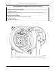
Mechanical Components:
Hard-anodized (black), machined aluminum vacuum chamber with integrated handle/ring stand
assembly. Chamber end closure mated to main vacuum shroud body by means of captive o-ring seal
and spring-loaded, quick-release clamps. Incorporates cold stage radiation shield. Includes MTD-100
high efficiency continuous flow cryostat with exhaust gas heater and bayonet receptacle.
NOTE: Device test set assembly kit hardware (Model 1520K) is ordered separately. This kit, configured
to initial DUT test requirements, consists of fanout boards with the required chip carrier socket, chip
carrier clamp assembly and cold finger pedestal. Refer to Chapter 6 for list of options and accessories.