
User`s manual


Lake Shore MTD Series Cryotest System User’s Manual
Motor Drive Controller I-3
I4.0 SERIAL INTERFACE OPERATING INSTRUCTIONS
The following are operating instructions used with the Motorized Drives Included With Carousel or
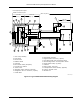
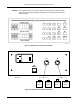
Filter Wheel Assemblies. The motor control unit has a built-in RS-232 Serial Interface. Connection is
made through a 9-pin D-connector mounted on the back panel of the controller. Data is transmitted
from the controller on Pin 3 and received on Pin 2. Pin 7 provides a common ground return. The data
format used is 8 data bits, 1 start bit, and 1 stop bit.
The following commands are used to control the unit through the serial interface. Every command
must be followed by a line feed (LF) and carriage return (CR).
To Separate the Stage Drive (J13):
Send ASCII D, ASCII S, ASCII LF, and an ASCII CR.
DS (LF) (CR)
To Engage the Stage Drive (J13):
DE (LF) (CR)
To Move the Carousel to a Desired Position: (Positions are 1 thru 8) (J14)
C1 (LF) (CR) This moves the carousel to position 1
C2 (LF) (CR) This moves the carousel to position 2
C3 (LF) (CR) This moves the carousel to position 3
C4 (LF) (CR) This moves the carousel to position 4
C5 (LF) (CR) This moves the carousel to position 5
C6 (LF) (CR) This moves the carousel to position 6
C7 (LF) (CR) This moves the carousel to position 7
C8 (LF) (CR) This moves the carousel to position 8
To Move the Filter Wheel to a Desired Position: (Positions are 1 thru 8) (J15)
F1 (LF) (CR) This moves the filter wheel to position 1
F2 (LF) (CR) This moves the filter wheel to position 2
F3 (LF) (CR) This moves the filter wheel to position 3
F4 (LF) (CR) This moves the filter wheel to position 4
F5 (LF) (CR) This moves the filter wheel to position 5
F6 (LF) (CR) This moves the filter wheel to position 6
F7 (LF) (CR) This moves the filter wheel to position 7
F8 (LF) (CR) This moves the filter wheel to position 8
To Move the Aperture Wheel to a Desired Position: (Positions are 1 thru 8) (J16)
A1 (LF) (CR) This moves the aperture wheel to position 1
A2 (LF) (CR) This moves the aperture wheel to position 2
A3 (LF) (CR) This moves the aperture wheel to position 3
A4 (LF) (CR) This moves the aperture wheel to position 4
A5 (LF) (CR) This moves the aperture wheel to position 5
A6 (LF) (CR) This moves the aperture wheel to position 6
A7 (LF) (CR) This moves the aperture wheel to position 7
A8 (LF) (CR) This moves the aperture wheel to position 8
It is important to remember that each command (one at a time) be followed by a line feed and carriage
return. The controller will respond to each command with one of four answers.
OK Command was successful
EO Requested command not an option (for units without all motor options)
E? Did not understand the request (unknown error)
ES Drive not separated error (if requesting to position the carousel while the drive
is still engaged)