
User`s manual


Lake Shore MTD Series Cryotest System User’s Manual
Motor Drive Controller I-1
APPENDIX I
MOTOR DRIVE CONTROLLER
I1.0 GENERAL
This appendix provides information on the Motor Drive Controller. The controller is described in
Paragraph I2.0. Operation is described in Paragraph I3.0. Finally, serial interface operating
instructions are provided in Paragraph I4.0.
I2.0 DESCRIPTION
The motor drive can control up to four independent stepping motors: the filter wheel, aperture wheel,
carousel wheel, and cold stage. The controller is configured to operate specific features depending on
the MTD model and options you purchased. You may not have all the functions available to you.
Before you plug the power cord to the power source, make sure all the other cables are connected
and the input power is set to the correct voltage. Rotate the voltage select wheel in the fuse housing to
change the voltage setting if necessary. Plug the power cord into the power receptacle.
Before operating the controller, open the cover of the MTD and make sure no packing material is left
in the vacuum space of the dewar. Follow the instructions in Paragraph I3.0 in local mode operate the
Motor Drive Controller to cycle through all the eight positions without installing any sample and filter.
CAUTION: Do not remove the wheels or drive gears. The assembly has been calibrated with the
Motor Drive controller.
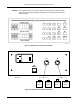
I3.0 OPERATION
Filter Wheel
. When the instrument is powered up, it will not remember the wheel location from the
last power down. Displace will indicate a letter “U.” Push the local button (LOC). Push the filter button
(FLTR) and enter button (ENT) to select function. For select position, push a number button (1 thru 8)
and the enter button (ENT). The motor will rotate the filter wheel to the selected position. After the
motor rotation, the display should read 11, 22, up to 88 depending on your selection. The filter position
reading is the first digit and the selected location is the second digit. They should be the same. The
controller reads the motor shaft position to determine the filter wheel location.
Aperture Wheel. Follow the same steps as detailed above except set function to aperture by pushing
the APER and ENT keys before selecting the position.
Carousel and Cold Stage. The carousel and cold stage must work together if the motorized option is
purchased. This option can be installed on an MTD-158 or MTD-268.
CAUTION: The stage must be separated from the carousel before operating the carousel motor.
The stage must be engaged before making any sample measurements.
Push stage up button (SEP) followed by the enter (ENT) button. The SEP light will light up to indicate
the separation of the stage from the carousel. Push the carousel function and enter buttons to select
carousel motor functions. Input position you want the carousel to go to same as it is done in operating
the Filter Wheel above. Engage the stage by pushing the ENG button and the enter (ENT) buttons.
I3.1 FILTER REMOVAL
In normal operations, the filter wheel assembly should not be removed from the drive shaft. To
change or install filters, remove the cover plate of the assembly. If you need to remove the assembly,
use the Controller to move the wheel to position 1 and follow the instructions in Appendix G.