
User`s manual


Lake Shore MTD Series Cryotest System User’s Manual
6-6 Options, Accessories, & Cables
ACCESSORIES (CONTINUED)
MODEL DESCRIPTION OF ACCESSORY
1522-Matrix
General Purpose Fanout Board – Special Version . A special version of the 1522 General
Purpose Fanout Board with a center pin grid matrix. The 1522-Matrix is a very versatile tool
which the Customer can use to configure an MTD-140 or -150 System to bread-board test any
custom device or module. There is a 24 x 24 pin grid matrix in the center of the board in place of
the standard Model 1522 center hole. The 576 holes in the pin grid matrix are 0.04 inch diameter
and are through-plated. The 100 signal lead traces are terminated with bifurcated pins around
the periphery. The 1522-Matrix board is installed by mounting it directly on the interface board
fingers and clamping it in place with the fanout board retaining ring. When installed in the MTD
System, the bifurcated pins are connected to the 100 coaxial signal lines.
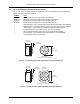
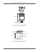
Installation: The Customer configures or modifies the board to accommodate the requirements
of the custom device to be tested. The Customer supplies the cold pedestal to provide the
thermal interface between the test device and the cold plate of the MTD system and provides the
clamp assembly to hold the custom test device against the cold pedestal. In a typical installation,
the MTD System user makes a cold pedestal and a clamp assembly appropriately sized for the
device to be tested, and cuts a hole in the fanout board grid matrix to fit this cold pedestal. The
socket/carrier for the custom device, if applicable, is mounted on the board over the cold
pedestal hole. The remainder of the pin grid matrix is used to bread-board the DUT connections
to the signal line bifurcated pins on the periphery of the card.
1550
DT-470 Sensor and Chip Heater Pre-Mounted in a Customer-Supplied Leadless Chip
Carrier (LCC) Mounting Base. This is a service provided by Lake Shore for Customers who want
one of their own LCC mounting bases configured with a temperature sensor and heater. This
accessory normally uses a Lake Shore Model DT-470-SD-12A silicon diode cryogenic
temperature sensor. Please contact Lake Shore for further information on this service.
1620
Four 25-Lead Ribbon Cables. A set of four 25-lead ribbon coax cables terminated in Insulation
Displacement Contact (IDC) style 50 pin (0.1 x 0.1 inch spacing) female socket headers on both
ends. Length is 1 meter (3 feet). The female socket headers are compatible with the male sockets
in the 1025 Breakout Box and the 25-line/50-pin vacuum feedthrough connectors on all models of
the MTD System. Compatible with the Model 1025 Breakout Box and 25 line/50 pin vacuum
feedthrough connectors on most MTD Systems. Specifications are listed below.
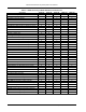
Electrical Specifications:
Impedance: 50 ±3 Ohms
Capacitance: 31 pF/ft (304.8) nom.
Crosstalk Constant* (Adjacent Pair):
Far End 2%, Near End 4%
Crosstalk Constant* (All Other Lines):
Far End 0%, Near End 0%
Propagation Display: <1.6 ns/ft. (304.8)
Risetime Degredation (20-80%):
<400 ps/10 ft (305 m)
Attenuation (at 100 MHz):
<14 dB/100 ft (30.48 m)
* Terminated Cable Assembly
Dimensions are in inches with metric e
q
uivalents in
p
arenthesis
Mechanical Specifications:
Center Conductor: 28 AWG
(0.08-0.09 mm
2
) Cu
Insulation Coating: Alkyd Enamel
Dielectric: Polyproplylene
Dielectric Constant: 2.3 nom.
Diameter: 0.041 (1.04) nom.
Shield: Al Mylar Foil 0.00135
(0.03429) thick
Drain Conductor: 28 or 30 AWG
(0.09-0.05) mm
2
Tin Plated Cu
Jacket: PVC (Fr)
Color per EAI STD RS-359: Black
Centerline Spacing: 0.100 (2.54)
If you wish to buy Socket Strips and solder your own cables, mating socket connectors can be
ordered from Samtec, P.O. Box 1147, New Albany, IN 47151-1147, 812-944-6733. Different
styles are available. For 50 pins, we suggest the Hi-Temp 0.025-inch square Socket Strips P/N
SSW-125-04-G-D, and for 34 pins P/N SSW-117-04-G-D.
1630
Socket/BNC Cable Assembly. The 1630 provides the MTD user with the capability of making
convenient BNC connections to the individual signal lines in an MTD System. The 1630 consists
of 3 feet of coaxial ribbon cabling with connectors on each end. On one end is a 50-pin female
socket header which mates with the 25-line/50-pin vacuum feedthrus for the signal lines on all
MTD Systems. The other end of the cable has 25 individual female BNCs attached to the 25 coax
lines of the ribbon cable. The center pin is the conductor and case is the shield. Length is 1 meter
(3 feet). Electrical and mechanical specifications are as listed for the Model 1620.