
User`s manual


Lake Shore MTD Series Cryotest System User’s Manual
5-2 Troubleshooting
5.7 TRANSFER LINES
Lake Shore's transfer lines are shipped with the vacuum jacket evacuated. This is a result of the final
testing at the factory, and ensures a clean vacuum space. As a precaution against deterioration of the
vacuum which arises sometimes during transit or a prolonged storage periods, the vacuum jacket
should be re-evacuated prior to use. This is best done with a good pumping station (e.g., a cold-trapped
rotary/diffusion pumping station) capable of an ultimate pressure of approximately 10
-5
Torr. After
evacuation, the evacuation valve should be firmly closed, but care should be exercised to avoid
damaging the valve seat by over tightening.
When evacuation is initiated, ensure pressure on the pump side of the evacuation valve is lower than
the vacuum space pressure. This is done to avoid drawing oil vapor from the pump into the vacuum
space. Thus, one should not pump the vacuum jacket while liquid helium is passing through the inner
line, since the liquid helium could cryopump to a lower pressure than the pumping station in use.
The withdrawal tube of the transfer line has a built-in activated charcoal getter to help maintain excellent
vacuum when inserted in cryogen. It is important to maintain this space under vacuum at all times and
never allow helium gas or moist air into this space. In the event moisture or helium does accidentally
enter the space, a pumping station should be attached to the space for several days in order to bring the
pressure down to an acceptable level.
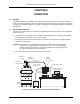
On completion of an experiment, the needle valve at the bottom of the transfer line withdrawal tube
should be closed, and a one way (or pressure relief) valve should be placed at the vacuum port on the
MTD. This prevents any cryogen from reaching the DUT mount and allows any cryogen remaining in the
inner line to vent safely outside the cryostat while stopping any air or moisture from entering the inner
line region. The storage dewar should then be de-pressurized, and the withdrawal tube removed in order
to reduce the heat input into the liquid inside the dewar.
5.7.1 TRANSFER LINE GENERAL PRECAUTIONS
It is important to maintain a vacuum in the transfer line at all times, and re-evacuate it whenever it
feels colder than normal during transfer. Evacuation should be done while the inner line is at room
temperature. Helium gas and moist air should never be allowed into the vacuum jacket.
• Do not bend the transfer line to a radius of less than 12 inches (30 cm).
• Do not over tighten the needle (flow control) valve at the bottom of the withdrawal tube.
• It is preferable to have an anti-oscillation device on your helium storage dewar, and keep the end
of the withdrawal about one centimeter above the bottom of the storage dewar.
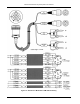
5.8 CABLE ASSEMBLIES
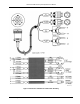
Details of the MTD Cable assemblies are provided in Figures 5-1 through 5-3. The Exhaust Gas Heater
Cable Assembly is defined in Figure 5-1. The P/N 8271-21M Cable Assembly in Figure 5-2 is used to
connect a MTD with either the Lake Shore Model 1015 Warm-Up Power Supply, DRC-91CA, or DRC-
93CA Temperature Controllers. The P/N 8271-30M Cable Assembly in Figure 5-3 is used to connect a
MTD with the Lake Shore Model 330 Autotuning Temperature Controller.
P-MTD-5-1.bmp
Figure 5-1. Definition of Exhaust Gas Heater Cable Assembly