
User`s manual


Lake Shore MTD Series Cryotest System User’s Manual
Operation 4-3
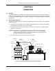
8. When cold gas begins escaping from transfer line bayonet fitting, remove clamp from the bottom of
the MTD cryostat, remove the metal cover, and insert the transfer line into the MTD cryostat
bayonet receptacle. Secure with bayonet clamp.
NOTE: Ensure rubber bayonet seal is installed before securing the bayonet clamp.
NOTE: If more than 5 minutes elapses without feeling any cold gas, there may be an ice plug in the
line. Depressurize the storage dewar and pull the withdrawal tube out of the storage dewar,
warm the transfer line with a heatgun, and purge the line with dry helium gas. (Refer to Chapter
5 – Troubleshooting if attempting a warm-start cool down and there appears to be no gas flow.)
9. Locate 3-pin connector at base of MTD cryostat. Attach the exhaust gas heater cable (provided).
Plug the other end of the cryostat heater to an AC power source after the MTD begins to cool.
Normally, if cooling at a good rate, you will see a slight white vapor coming from the MTD vent.
A sure sign of too rapid cooling is seeing liquid cryogen spitting from the MTD vent.
10. Connect provided Model 8271-XXM Instrumentation Cable to 19-pin instrumentation feedthrough
connector located on cryostat.
11. Connect other end of Instrumentation Cable to Temperature Controller. Refer to Figure 3-3 for
hookup to Model DRC-91CA or DRC-93CA or Figure 3-4 for hookup to Model 330 Autotuning
Temperature Controller.
CAUTION: Check to ensure that the proper sensor is connected to the control input channel on the
temperature controller and the correct heater plug is connected to the controller output.
Improper connections could cause damage due to applying heater power to one stage
while sensing temperature on the other stage.
NOTE: Consult appropriate Temperature Controller User's Manual for controller operation.
12. Wait for the MTD System to cool down to desired temperature. Once temperature is reached,
throttle back flow of cryogen. (One-half turn open is sufficient in most cases.)
13. Adjust setpoint on Temperature Controller to desired value. Temperature Controller will apply
current to heater of second stage to maintain temperature at setpoint. Consult Application Note
Fundamentals For Usage of Cryogenic Temperature Controllers normally included in Temperature
Controller User’s Manual for setting proportional, integral and derivative (PID) constants.
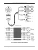
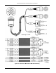
14. To connect Customer instrumentation, connect appropriate cables to four 50-pin feedthrough
connectors on vacuum chamber base plate. Connectors are labeled A, B, C, and D. A typical
50-pin connector is illustrated in Figure 4-3. MTD is now ready to perform tests.
NOTE: Although the instrumentation connectors have 50 pins, there are only 25 signal lines per
connector. Twenty-five signal lines times four connectors equals the one hundred
connections on a typical fanout board. When viewing the instrumentation connector as
shown in Figure 4-3, the default setup for a standard MTD-150 assigns the outer row of
25 pins for signals from the DUT. The inner row of 25 pins has connections for the shield.
The shield pin corresponds to the signal pin directly adjacent to it.
NOTE: Other wiring configurations are possible per Customer Order. Consult the factory with
questions concerning alternative wiring configurations.