
User`s manual


Lake Shore MTD Series Cryotest System User’s Manual
Installation 3-7
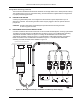
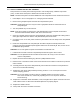
P-MTD-3-5.bmp
Figure 3-5. Retaining Ring and Fanout Board
4. Install the fanout board so that the cold pedestal protrudes through the device socket.
CAUTION: The cold pedestal and fanout board should not bind. Do not try to force the socket
over the cold pedestal.
5. Replace the fanout board retaining ring with the 4 flat head screws.
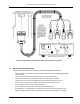
6. Place the DUT in the device socket on the fanout board and ensure that its contacts line up with the
socket contacts.
7. Carefully place the chip carrier clamp assembly over the DUT and check that it compresses the
DUT into the socket without binding.
8. Replace the chip carrier clamp assembly mounting screws in a 1–2–3–4 sequence to ensure
uniform clamping pressure.
CAUTION: Do not over tighten mounting screws or completely tighten one at a time. Tighten
each screw ½ turn, continuously repeating the 1–3–2–4 sequence until all four screws
are snug.
9. Replace the cooled filter wheel assemblies, if used, and tighten the 3 captive screws and the drive
shaft collett lock hex nut. Ensure that the filters/apertures are properly aligned.
10. Replace the radiation shield.
11. Clamp down the vacuum chamber end closure.