
User`s manual


Lake Shore MTD Series Cryotest System User’s Manual
Introduction 1-11
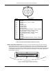
TEST SET ASSEMBLY: Consists of the cold pedestal, fanout board, and chip carrier clamp assembly.
TRANSFER LINE: The optional Model 1205 transfer line is a conventional, flexible, vacuum-insulated
line consisting of a long rigid withdrawal tube which can be inserted into a LHe storage vessel or
modified LN
2
container. The withdrawal tube contains a filter to prevent foreign matter from plugging
the small diameter inner tube. A LN
2
transfer line is available. Refer to Chapter 6 – Options and
Accessories for additional details.
VACUUM CHAMBER BASE PLATE: All electrical feedthrus and mechanical linkages pass through the
base plate which is located on the bottom of the vacuum chamber. The four 25-line feedthru
connectors and provisions for installation of the optional filter wheel assembly drive shafts are also
found here.
VACUUM CHAMBER END CLOSURE: When removed, allows access to testing area. Held in place by
four pull-down clamps. Also, embedded in chamber end closure is an o-ring. It assures a vacuum
tight fit between the main chamber and chamber end closure. A two inch window is present in order
to illuminate the DUT during testing.
VACUUM CHAMBER: Black anodized machined aluminum cylinder which encloses the cryostat cold
finger. Consists of main chamber, chamber end closure and vacuum chamber base plate.
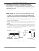
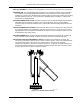
VACUUM PORT AND VACUUM PUMPOUT VALVE: Located on the underside of the dewar, the
vacuum port and pumpout valve is used to connect a vacuum pump in order to evacuate/isolate the
vacuum chamber space. It also serves as a pressure relief in case of vacuum chamber
overpressure. Operation of the valve is shown in Figure 1-10. To operate, the handle pushed up to
the seat and rotated clockwise (3 to 4 revolutions) to thread into the valve seat. Pull out the handle
to open (vent) the vacuum space and push in to close.
F-MTD-1-10.eps
Figure 1-10. Vacuum Valve Cutaway