User's Manual MTD Series Modular Test Dewar Cryotest System The MTD Series Consists Of: MTD-140 – Single-position, pour-fill dewar system MTD-144 – Four-position, LCC pour-fill dewar system MTD-150B – Single-position, continuous-flow cryostat system MTD-154 – Four-position, continuous-flow cryostat MTD-158 – Eight-position, continuous-flow cryostat MTD-260B – Single-position, closed-cycle refrigerator Lake Shore Cryotronics, Inc. 575 McCorkle Blvd.
Lake Shore MTD Series Cryotest System User’s Manual LIMITED WARRANTY Lake Shore Cryotronics, Inc. (henceforth Lake Shore), the manufacturer, warrants this product to be free from defects in material and workmanship for a period of twelve (12) months from the date of shipment.
Lake Shore MTD Series Cryotest System User’s Manual TABLE OF CONTENTS Chapter/Paragraph Title Page 1 INTRODUCTION ....................................................................................................................................1-1 1.0 General................................................................................................................................1-1 1.1 MTD Cryotest System General Description.......................................................................
Lake Shore MTD Series Cryotest System User’s Manual TABLE OF CONTENTS (Continued) Chapter/Paragraph 5.5 5.6 5.7 5.7.1 5.8 6 Title Page Unable To Reach Cold Terminal Temperature................................................................... 5-1 No Response To Control Heater......................................................................................... 5-1 Transfer Lines .....................................................................................................................
Lake Shore MTD Series Cryotest System User’s Manual LIST OF ILLUSTRATIONS Figure No. 1-1 1-2 1-3 1-4 1-5 1-6 1-7 1-8 1-9 1-10 3-1 3-2 3-3 3-4 3-5 4-1 4-2 4-3 5-1 5-2 5-3 6-1 6-2 6-3 6-4 C-1 E-1 F-1 G-1 H-1 H-2 I-1 I-2 Title Page Model MTD-150B with Vacuum Shroud & Radiation Shield Removed ............................................1-3 Typical MTD-150 Cryotest System ...................................................................................................1-4 Typical Model MTD-150 Cutaway.....
Lake Shore MTD Series Cryotest System User’s Manual This Page Intentionally Left Blank iv Table of Contents
Lake Shore MTD Series Cryotest System User’s Manual CHAPTER 1 INTRODUCTION 1.0 GENERAL This chapter provides an introduction to the Modular Test Dewar (MTD) Cryotest System. The MTD System was designed and manufactured in the United States of America by Lake Shore Cryotronics, Inc. The MTD Series consists primarily of the Model MTD-150, a Single-Position Continuous Flow Cryostat System. Other configurations can be made from the basic MTD-150 unit.
Lake Shore MTD Series Cryotest System User’s Manual Table 1-1. Model MTD-150 Cryotest System Specifications _________________________________________________________________________________________________________________________________________________________________________________________________________________________________ Temperature Range: Less than 4 kelvin to 400 kelvin with liquid helium (LHe), or from 77 kelvin to 400 kelvin with liquid nitrogen (LN2).
Lake Shore MTD Series Cryotest System User’s Manual Table 1-1. Model MTD-150 Cryotest System Specifications (Continued) _________________________________________________________________________________________________________________________________________________ Temperature Measurement and Control: DT-470-CU-12A silicon diode temperature sensors and 25 Ω heaters mounted on the first and second stage heat exchangers.
Lake Shore MTD Series Cryotest System User’s Manual 1.1.1 MTD CRYOTEST SYSTEM APPLICATION The modular design of the MTD reduces the time required for reconfiguration, device setup and cycle testing.
Lake Shore MTD Series Cryotest System User’s Manual 1.1.4 RAPID TEMPERATURE CYCLING CAPABILITY Rapid temperature cycling between ambient and test temperatures assures a higher device throughput. A two-stage, continuous-flow cryostat utilizes two high-efficiency heat exchangers to provide rapid cooling of the sample mounting structure, radiation shield, and heat sinks. The cryostat can be operated with either liquid helium (LHe) or liquid nitrogen (LN2). Temp_Chart.bmp 1.1.
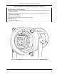
Lake Shore MTD Series Cryotest System User’s Manual Chip Carrier Socket Window Filter Mount Chip Carrier Chip Clamp Assy Vacuum Shroud Cover Fanout Board Assy Quick Release Clamps, 4 Plcs Radiation Shield Intermediate Vacuum Shroud Coax Heat Sink G-10 Phenolic Spacers Micro Coax, 100 Plcs. Heaters in Both Stages Temp. Sensor in Both Stages Coax Feedthru Connector, 4 Plcs Lake Shore MTD-100 Cryostat Handle/Ring Stand Assy. F-MTD-1-03.eps Figure 1-3.
Lake Shore MTD Series Cryotest System User’s Manual 1.1.9 PRECISE MONITORING AND CONTROL OF TEMPERATURE OVER A WIDE RANGE Select from Lake Shore’s full line of temperature controllers and sensors to complete system operational requirements. Shown is the Model 330 temperature controller, which offers Autotuning of Proportional, Integral, and Derivative (PID) parameters, front panel programming.
Lake Shore MTD Series Cryotest System User’s Manual EXHAUST GAS HEATER: The exhaust gas heater warms the exhaust gas to room temperature before exiting the cryostat. This minimizes frosting on the MTD-100 Cryostat and prevents premature hardening of the o-rings. A flow control valve may be connected to the exhaust port to apply back pressure to the gas flow, enhancing the efficiency of cryogen consumption. A power cable is provided with the MTD System. See Figure 1-5 for cryostat connector pin definitions.
Lake Shore MTD Series Cryotest System User’s Manual P-MTD-1-07.bmp Figure 1-7. Typical Square Fanout Board (Top View) FIRST STAGE HEAT EXCHANGER: Located on the cryostat cold finger. This stage provides cooling to the radiation shield and signal lead heat sinks. A DT-470 series silicon diode temperature sensor and 2 cartridge heaters are mounted to this stage for temperature monitoring, temperature control and rapid warm-up. FLOW VALVE: Controls flow of cryogen through the transfer line.
Lake Shore MTD Series Cryotest System User’s Manual M L K A N U J B P V T H C R S G D E F P-MTD-1-08.bmp PIN NO.
Lake Shore MTD Series Cryotest System User’s Manual TEST SET ASSEMBLY: Consists of the cold pedestal, fanout board, and chip carrier clamp assembly. TRANSFER LINE: The optional Model 1205 transfer line is a conventional, flexible, vacuum-insulated line consisting of a long rigid withdrawal tube which can be inserted into a LHe storage vessel or modified LN2 container. The withdrawal tube contains a filter to prevent foreign matter from plugging the small diameter inner tube.
Lake Shore MTD Series Cryotest System User’s Manual This Page Intentionally Left Blank 1-12 Introduction
Lake Shore MTD Series Cryotest System User’s Manual CHAPTER 2 PRE-INSTALLATION 2.0 GENERAL This chapter discusses inspection, unpacking, and reshipment aspects of the MTD Cryotest System. Inspection and unpacking are detailed in Paragraph 2.1, repackaging for shipment in Paragraph 2.2, general installation precautions in Paragraph 2.3, electrostatic discharge in Paragraph 2.4, safety summary in Paragraph 2.5, and safety symbols in Paragraph 2.6.
Lake Shore MTD Series Cryotest System User’s Manual General Installation Precautions (Continued) Do not install or service equipment alone. Personnel shall not under any circumstances reach into or enter any enclosure for the purpose of servicing or adjusting the equipment without immediate presence or assistance of another person capable of rendering aid. 2.4 ELECTROSTATIC DISCHARGE Damage can occur to electronic parts, assemblies, and equipment from electrostatic discharge (ESD).
Lake Shore MTD Series Cryotest System User’s Manual 2.5 SAFETY SUMMARY The following general safety precautions must be observed during all phases of operation, service, and repair of this instrument. Failure to comply with these precautions or with specific warnings elsewhere in this manual violates safety standards of design, manufacture, and intended use of the instrument. Lake Shore Cryotronics, Inc. assumes no liability for the customer's failure to comply with these requirements.
Lake Shore MTD Series Cryotest System User’s Manual This Page Intentionally Left Blank 2-4 Unpacking & Inspection
Lake Shore MTD Series Cryotest System User’s Manual CHAPTER 3 INSTALLATION 3.0 GENERAL This chapter provides instructions and equipment required to install the MTD Cyrotest System. Environmental requirements are detailed in Paragraph 3.1, system power and ground requirements in Paragraph 3.2, physical support requirements in Paragraph 3.3, liquid cryogen requirements in Paragraph 3.4, storage dewar pressurizing in Paragraph 3.5, hookup of the exhaust gas heater in Paragraph 3.
Lake Shore MTD Series Cryotest System User’s Manual Environmental Requirements (Continued) It is imperative that adequate ventilation of work area be provided. This will prevent build up of potentially life-threatening concentrations of helium and nitrogen gas. Refer to Appendix E for further information. Oxygen content monitor/alarms should be installed near the work site to warn against low oxygen levels.
Lake Shore MTD Series Cryotest System User’s Manual Storage Dewar Pressuring (Continued) The transfer line withdrawal tube should be sealed at the storage dewar neck to allow pressure build up. The standard seal is a ½-inch compression fitting. Consult instructions supplied with the storage dewar for proper pressurizing procedure. 3.6 EXHAUST GAS HEATER A three prong detachable power cord configured for the Customer’s power requirements (110 or 220 VAC) is included.
Lake Shore MTD Series Cryotest System User’s Manual P-MTD-3-3.bmp Figure 3-3.
Lake Shore MTD Series Cryotest System User’s Manual P-MTD-3-4.bmp Figure 3-4. MTD System Hookup to the Model 330 Temperature Controller 3.8 MISCELLANEOUS PRECAUTIONS The following are miscellaneous precautions associated with MTD System operation. • When necessary, the transfer line should be evacuated with a nitrogen-trapped diffusive-type vacuum system. • The transfer line should not be bent to less than a 12-inch (30 cm) radius.
Lake Shore MTD Series Cryotest System User’s Manual 3.9 INSERTING A DEVICE UNDER TEST (DUT) The MTD-150 System should be stabilized at room temperature and the transfer line removed. 1. Open the vacuum pumpout valve on cryostat to vent system. 2. Release the 4 pull-down clamps and remove the vacuum chamber end closure. NOTE: Place vacuum chamber end closure so that the o-ring is face up to prevent damage. 3. Remove radiation shield by unscrewing the six captive socket head screws. 4.
Lake Shore MTD Series Cryotest System User’s Manual P-MTD-3-5.bmp Figure 3-5. Retaining Ring and Fanout Board 4. Install the fanout board so that the cold pedestal protrudes through the device socket. CAUTION: The cold pedestal and fanout board should not bind. Do not try to force the socket over the cold pedestal. 5. Replace the fanout board retaining ring with the 4 flat head screws. 6.
Lake Shore MTD Series Cryotest System User’s Manual 3.11 HOW TO CHANGE THE TEST SET ASSEMBLY This procedure is necessary when switching a Dual In-Line Package (DIP), Leadless Chip Carrier (LCC), or other device that require a different fanout board and socket. NOTE: The MTD-150 System should be stabilized at room temperature and the transfer line removed. 1. Follow Steps 1 thru 3 in Paragraph 3.10 – Changing the Fanout Board. 2. Remove the 4 gold plated posts which hold the cold pedestal in place.
Lake Shore MTD Series Cryotest System User’s Manual CHAPTER 4 OPERATION 4.0 GENERAL This chapter describes the operation and shutdown of the MTD Cryotest System. Be sure to read the entire manual before continuing. Also ensure that all instruments are working correctly prior to operating the system. MTD System Operation is provided in Paragraph 4.1. MTD System Shutdown is provided in Paragraph 4.2. 4.1 MTD SYSTEM OPERATION The follow is a typical procedure for operation of the MTD Cryotest System.
Cryotronics Lake Shore Lake Shore MTD Series Cryotest System User’s Manual C-MTD-4-2.eps Figure 4-2. Typical MTD with Model 1705 Horizontal Mount Cradle Assembly CAUTION: It is important to stabilize the MTD to prevent the system from tipping over or falling. The preferred method is the use of the optional Model 1705 Horizontal Cradle Mount Assembly. An alternative method would be to clamp the MTD Handle/Ring Stand Assembly to the table surface. 4.
Lake Shore MTD Series Cryotest System User’s Manual 8. When cold gas begins escaping from transfer line bayonet fitting, remove clamp from the bottom of the MTD cryostat, remove the metal cover, and insert the transfer line into the MTD cryostat bayonet receptacle. Secure with bayonet clamp. NOTE: Ensure rubber bayonet seal is installed before securing the bayonet clamp. NOTE: If more than 5 minutes elapses without feeling any cold gas, there may be an ice plug in the line.
Lake Shore MTD Series Cryotest System User’s Manual P-MTD-4-3.bmp Figure 4-3. Typical 50-Pin Connector 4.2 MTD SYSTEM SHUTDOWN At the completion of the test, the following steps will ensure proper shutdown of the system and avoid contamination of the DUT by water vapor or other contaminants. 1. Shut off flow of cryogen by closing transfer line flow valve. CAUTION: Do not over-tighten the flow valve. Over-tightening may damage the valve seat. 2.
Lake Shore MTD Series Cryotest System User’s Manual CHAPTER 5 TROUBLESHOOTING 5.0 GENERAL This chapter covers possible difficulties that may occur. Please read the entire chapter before attempting to troubleshoot the MTD Cryotest System. 5.1 NO CRYOGEN FLOW AND NO COOLING During a warm start cool down, latent heat must be removed from the transfer line. Therefore, the flow rate may be low during this “flat” period and difficult to observe.
Lake Shore MTD Series Cryotest System User’s Manual 5.7 TRANSFER LINES Lake Shore's transfer lines are shipped with the vacuum jacket evacuated. This is a result of the final testing at the factory, and ensures a clean vacuum space. As a precaution against deterioration of the vacuum which arises sometimes during transit or a prolonged storage periods, the vacuum jacket should be re-evacuated prior to use. This is best done with a good pumping station (e.g.
Lake Shore MTD Series Cryotest System User’s Manual P-MTD-5-2.bmp Figure 5-2.
Lake Shore MTD Series Cryotest System User’s Manual P-MTD-5-3.bmp Figure 5-3.
Lake Shore MTD Series Cryotest System User’s Manual CHAPTER 6 OPTIONS AND ACCESSORIES 6.0 GENERAL This chapter provides lists of MTD Cryotest System options and accessories. Options are detailed in Paragraph 6.1. Accessories are detailed in Paragraph 6.2. Finally, a list of associated Lake Shore Publications is provided in Paragraph 6.3. 6.1 MTD CRYOTEST SYSTEM OPTIONS A list of major MTD Cryotest System Model numbers is provided below.
Lake Shore MTD Series Cryotest System User’s Manual ACCESSORIES (CONTINUED) MODEL 6-2 DESCRIPTION OF ACCESSORY 1025 Breakout Box with 100 BNC Connectors. Often there is a need to perform simple electrical tests on individual elements of the DUT that are not as accessible in automated testing due to the random nature of the test requirements. Breakout boxes provide the means to accomplish this. Breakout boxes are comprised of a set of floating BNC connectors, one for each signal line.
Lake Shore MTD Series Cryotest System User’s Manual ACCESSORIES (CONTINUED) MODEL 1220-50 DESCRIPTION OF ACCESSORY Liquid Nitrogen 50 Liter Storage Dewar. The Storage Dewar is a rugged 50-liter selfpressurized dewar configured to be compatible with the Model 1210 and 1215 Transfer Lines. The top of the dewar is equipped with a port which will accommodate the transfer line 0.
Lake Shore MTD Series Cryotest System User’s Manual ACCESSORIES (CONTINUED) MODEL DESCRIPTION OF ACCESSORY 1402 Dual Motorized Driver and Controller Assembly. Motorized driver and controller assemblies are used with the Cooled Filter/Aperture Wheel Assemblies whenever fully automated, computer controlled device testing is required. They can also be used for lifting and rotating the test device carousel in the MTD-158 Carousel System.
Lake Shore MTD Series Cryotest System User’s Manual ACCESSORIES (CONTINUED) MODEL 1521K DESCRIPTION OF ACCESSORY Device Test Set Assembly Kit. The Model 1521K Series of test set assembly kits are complete device kits incorporating the Model 1521 personality-style fanout boards with specific device socket, a clamp assembly, and the appropriate cold finger pedestal—all gold plated.
Lake Shore MTD Series Cryotest System User’s Manual ACCESSORIES (CONTINUED) MODEL DESCRIPTION OF ACCESSORY 1522-Matrix General Purpose Fanout Board – Special Version . A special version of the 1522 General Purpose Fanout Board with a center pin grid matrix. The 1522-Matrix is a very versatile tool which the Customer can use to configure an MTD-140 or -150 System to bread-board test any custom device or module.
Lake Shore MTD Series Cryotest System User’s Manual ACCESSORIES (CONTINUED) MODEL DESCRIPTION OF ACCESSORY 1705 Horizontal Cradle Mount Assembly. The heavy duty, horizontal cradle mount assembly securely clamps the MTD unit in a horizontal, side-looking position. Construction is 12.7 cm (0.5 inch) aluminum plate with black-anodized finish. Compatible with all MTD Models; standard with the Model MTD-158. 1710 Gimbal Base Assembly.
Lake Shore MTD Series Cryotest System User’s Manual Table 6-1.
Lake Shore MTD Series Cryotest System User’s Manual 6.3 LIST OF ASSOCIATED LAKE SHORE PUBLICATIONS A list of Lake Shore Technical Publications, Application Notes, and literature that may be associated with the MTD Series are listed as follows: NUMBER TITLE MAN-1015 MAN-330 MAN-91C MAN-93C — — — Model 1015 Warm-Up Power Supply User’s Manual. Model 330 Autotuning Temperature Controller User’s Manual. Model DRC-91CA Temperature Controller User’s Manual. Model DRC-93CA Temperature Controller User’s Manual.
Lake Shore MTD Series Cryotest System User’s Manual 1.125 in. (28.6 mm) A M B C D P N R E V S F G L U T K J H 1.75 in. (44.45 mm) Mating Connector for 9005-014 & -016 (Shown Assembled: Hardware for Attaching Connector to Customer-Supplied Cable is Included ) C-MTD-6-3 Figure 6-3. Mating Connector (P/N 9005-015) 1.25 in. (31.75 mm) 1.25 in. (31.75 mm) O-ring (4) 4-40 Holes Aluminum Block 0.83 in. (21.03 mm) Female 3/8" NPT Mating Adapter For Mounting P/N 9005-016 in 3/8 in. (0.
Lake Shore MTD Series Cryotest System User’s Manual APPENDIX A GLOSSARY OF TERMINOLOGY absolute zero. The temperature of –273.15 °C, or –459.67 °F, or 0 K, thought to be the temperature at which molecular 1 motion vanishes and a body would have no heat energy. 2 accuracy. The degree of correctness with which a measured value agrees with the true value. electronic accuracy. The accuracy of an instrument independent of the sensor. sensor accuracy.
Lake Shore MTD Series Cryotest System User’s Manual boiling point. The temperature at which a substance in the liquid phase transforms to the gaseous phase; commonly refers to the boiling point at sea level and standard atmospheric pressure. CalCurve Service. The service of storing a mathematical representation of a calibration curve on an EEPROM or installed in a Lake Shore instrument. Previously called a Precision Option. calibration.
Lake Shore MTD Series Cryotest System User’s Manual 2 digital data. Pertaining to data in the form of digits or interval quantities. Contrast with analog data. dimensionless sensitivity. Sensitivity of a physical quantity to a stimulus, expressed in dimensionless terms. The dimensionless temperature sensitivity of a resistance temperature sensor is expressed as Sd = (T/R)(dR/dT) which is also equal to the slope of R versus T on a log-log plot, that is Sd = d lnR / d lnT.
Lake Shore MTD Series Cryotest System User’s Manual ground. A conducting connection, whether intentional or accidental, by which an electric circuit or equipment is connected to the earth, or to some conducting body of relatively large extent that serves in place of the earth.
Lake Shore MTD Series Cryotest System User’s Manual liquid helium (LHe). Used for low temperature and superconductivity research: minimum purity 99.998%. Boiling point at 1 atm = 4.2 K. Latent heat of vaporization = 2.6 kilojoules per liter. Liquid density = 0.125 kilograms per liter. EPA Hazard Categories: Immediate (Acute) Health and Sudden Release of Pressure Hazards DOT Name: Helium, Refrigerated Liquid DOT Label: Nonflammable Gas DOT Class: Nonflammable Gas DOT ID No: UN 1963 liquid nitrogen (LN2).
Lake Shore MTD Series Cryotest System User’s Manual normalized sensitivity. For resistors, signal sensitivity (dR/dT) is geometry dependent; i.e., dR/dT scales directly with R; consequently, very often this sensitivity is normalized by dividing by the measured resistance to give a sensitivity, s T, in percent change per kelvin. sT = (100/R) (dR/dT) %K, where T is temperature in kelvin and R is resistance in ohms. normally closed (N.C.). A term used for switches and relay contacts.
Lake Shore MTD Series Cryotest System User’s Manual remanence. The remaining magnetic induction in a magnetic material when the material is first saturated and then the applied field is reduced to zero. The remanence would be the upper limit to values for the remanent induction. Note that no strict convention exists for the use of remanent induction and remanence and in some contexts the two terms may be used interchangeably. remanent induction.
Lake Shore MTD Series Cryotest System User’s Manual susceptance. In electrical terms, susceptance is defined as the reciprocal of reactance and the imaginary part of the complex representation of admittance: [suscept(ibility) + (conduct)ance]. susceptibility (χ χ). Parameter giving an indication of the response of a material to an applied magnetic field. The susceptibility is the ratio of the magnetization (M) to the applied field (H). χ = M/H.
Lake Shore MTD Series Cryotest System User’s Manual APPENDIX B UNITS FOR MAGNETIC PROPERTIES Table B-1.
Lake Shore MTD Series Cryotest System User’s Manual Table B-2. Recommended SI Values for Physical Constants Quantity Symbol Permeability of Vacuum µ0 Value (SI units) 4π x 10 H m Speed of Light in Vacuum c 2.9979 x 10 m s Permitivity of Vacuum ε0 = (µ0c ) Fine Structure Constant, µ0ce2/2h α -1 α Elementary Charge e -7 -1 8 2 -1 8.8542 x 10 -12 -1 Fm -1 0.0073 137.0360 1.6022 x 10 Plank's Constant h h = h/2π Avogadro's Constant NA C Atomic Mass Unit lu = (10 kg mol /NA -1 6.
Lake Shore MTD Series Cryotest System User’s Manual APPENDIX C TEMPERATURE SCALES C1.0 DEFINITION Temperature is a fundamental unit of measurement which describes the kinetic and potential energies of the atoms and molecules of bodies. When the energies and velocities of the molecules in a body are increased, the temperature is increased whether the body is a solid, liquid, or gas. Thermometers are used to measure temperature.
Lake Shore MTD Series Cryotest System User’s Manual Table C-1. Temperature Conversion Table °F -459.67 -454 -450 -449.67 -441.67 -440 -439.67 -436 -430 -429.67 -423.67 -420 -419.67 -418.00 -410 -409.67 -405.67 -400 -399.67 -390 -389.67 -387.67 -382 -380 -379.67 -370 369.67 -364 -360 -359.67 -351.67 -350 -349.67 -346 -340 -339.67 -333.67 -330 -329.67 -328 -320 -319.67 -315.67 -310 -309.67 -300 -299.67 -297.67 C-2 °C -273.15 -270 -267.78 -267.59 -263.15 -262.22 -262.04 -260 -256.67 -256.48 -253.15 -251.
Lake Shore MTD Series Cryotest System User’s Manual APPENDIX D TABLE OF ELEMENTS Element Actinium Aluminum Americium Antimony Argon Arsenic Astatine Barium Berkelium Beryllium Bismuth Boron Bromine Cadmium Cesium Calcium Californium Carbon Cerium Chlorine Chromium Cobalt Copper Curium Dysprosium Einsteinium Erbium Europium Fermium Fluorine Francium Gadolinium Gallium Germanium Gold Hafnium Helium Holmium Hydrogen Indium Iodine Iridium Iron Krypton Lanthanum Lawrencium Lead Lithium Lutetium Magnesium Mangan
Lake Shore MTD Series Cryotest System User’s Manual This Page Intentionally Left Blank D-2 Table of Elements
Lake Shore MTD Series Cryotest System User’s Manual APPENDIX E HANDLING OF LIQUID HELIUM AND NITROGEN E1.0 GENERAL Liquid Helium (LHe) and liquid nitrogen (LN2) are used in the operation of the MTD Series System. Although not explosive, there are a number of safety considerations to keep in mind in the handling of LHe and LN2. E2.0 PROPERTIES LHe and LN2 are colorless, odorless, and tasteless gases.
Lake Shore MTD Series Cryotest System User’s Manual E4.0 LIQUID HELIUM AND NITROGEN SAFETY PRECAUTIONS Transferring LHe and LN2 and operation of the storage dewar controls should be in accordance with the manufacturer/supplier’s instructions. During this transfer, it is important that all safety precautions written on the storage dewar and recommended by the manufacturer be followed. WARNING: Liquid helium and liquid nitrogen are potential asphyxiants and can cause rapid suffocation without warning.
Lake Shore MTD Series Cryotest System User’s Manual APPENDIX F POUR-FILL DEWAR F1.0 GENERAL This appendix will provide general information on the optional pour-fill dewar for the MTD Cryotest System. F2.0 DESCRIPTION The operation of the pour-fill dewar is similar to the operation of the standard MTD-150. Internal differences are illustrated in Figure F-1. The main chapters of this manual should be read before using-the pour-fill system. The following differences should be noted between the systems. 1.
Lake Shore MTD Series Cryotest System User’s Manual P-MTD-F-1.bmp Figure F-1.
Lake Shore MTD Series Cryotest System User’s Manual APPENDIX G FILTER WHEEL ASSEMBLIES G1.0 GENERAL This appendix will describe typical operation of the optional filter wheel assembly used with the MTD Cryotest System. G2.0 DESCRIPTION Filter wheel assemblies allow optical testing of infrared focal plane arrays with multiple filters. The filter wheel is coupled via a drive shaft assembly which protrudes through the vacuum chamber base plate.
Lake Shore MTD Series Cryotest System User’s Manual G3.0 ASSEMBLY INSTALLATION The MTD-150 System should be stabilized at room temperature and the transfer line removed. The system should be stood upright on its ring stand. 1. Open the vacuum pumpout valve to vent system. 2. Release the 4 pull-down clamps and remove the vacuum chamber end closure. NOTE: Place vacuum chamber end closure so that the o-ring is face up to prevent damage. 3.
Lake Shore MTD Series Cryotest System User’s Manual APPENDIX H Model MTD-260B Cryotest Workstation H1.0 GENERAL This appendix provides information on the Model MTD-260B Closed-Cycle 20 K Cryotest Workstation with a closed-cycle refrigerator. The Model MTD-260B is used for testing focal plane arrays and integrated circuits from <20 K to 350 K without the use of cryogens. The user area is identical to the Model MTD-150B described in the main portion of this manual. H2.
Lake Shore MTD Series Cryotest System User’s Manual H3.0 SPECIFICTIONS The following are specifications for the Model MTD-260B Cryotest Workstation: • Lateral displacement when the refrigerator is operating is <0.001 inch with 2 millisecond pulse width. The expander piston frequency is 2.78 Hertz. • The cooling capacity is as follows: At 10 K, the cooling capacity is ≈1.5 watts At 15 K, the cooling capacity is ≈5.2 watts At 20 K, the cooling capacity is ≈7.8 watts 300 250 .
Lake Shore MTD Series Cryotest System User’s Manual * Cover height depends on options installed or Customer request. 58.4 cm (23 in.) 11.4 cm (4.5 in.) * 1 2 15.2 cm (6 in.) 7 4 5 3 15.2 cm (6 in.) 6 8 21 30.5 cm (12 in.) 20 12 9 10 13 19 18 17 16 15 14 1. DUT Clamp Assembly 2. DUT Socket 3. Fanout Board 4. Radiation Shield 5. Cold Plate 6. Micro-Coaxial Cable (100 places) 7. Pump-Out Port, NW-25 8. Vacuum Valve 9. Refrigerator Motor Electrical Connection 10.
Lake Shore MTD Series Cryotest System User’s Manual This Page Intentionally Left Blank H-4 Model MTD-260 Cryotest Workstation
Lake Shore MTD Series Cryotest System User’s Manual APPENDIX I MOTOR DRIVE CONTROLLER I1.0 GENERAL This appendix provides information on the Motor Drive Controller. The controller is described in Paragraph I2.0. Operation is described in Paragraph I3.0. Finally, serial interface operating instructions are provided in Paragraph I4.0. I2.0 DESCRIPTION The motor drive can control up to four independent stepping motors: the filter wheel, aperture wheel, carousel wheel, and cold stage.
Lake Shore MTD Series Cryotest System User’s Manual CAUTION: Do not operate the motor when the wheels are dismounted from the drive shaft. The wheel must be indexed properly with respect to the drive shaft for the unit to operate properly. P-MTD-I-1.bmp Figure I-1. Motor Drive Controller Front Panel 120Vac J10 J9 J11 SERIAL I/O 1 Motor Drive Controller Rear View J15 J16 J14 J13 Filter Motor Aperture Motor Carousel Motor Stage Motor C-MTD-I-2.eps Figure I-2.
Lake Shore MTD Series Cryotest System User’s Manual I4.0 SERIAL INTERFACE OPERATING INSTRUCTIONS The following are operating instructions used with the Motorized Drives Included With Carousel or Filter Wheel Assemblies. The motor control unit has a built-in RS-232 Serial Interface. Connection is made through a 9-pin D-connector mounted on the back panel of the controller. Data is transmitted from the controller on Pin 3 and received on Pin 2. Pin 7 provides a common ground return.
Lake Shore MTD Series Cryotest System User’s Manual This Page Intentionally Left Blank I-4 Motor Drive Controller
Lake Shore MTD Series Cryotest System User’s Manual APPENDIX J STANDARD CURVE 10 Standard Curve 10: Measurement Current = 10 µA ±0.05% T (K) Voltage dV/dT (mV/K) T (K) Voltage dV/dT (mV/K) T (K) Voltage dV/dT (mV/K) 1.40 1.60 1.80 2.00 2.20 1.69812 1.69521 1.69177 1.68786 1.68352 –13.1 –15.9 –18.4 –20.7 –22.7 16.0 16.5 17.0 17.5 18.0 1.28527 1.27607 1.26702 1.25810 1.24928 –18.6 –18.2 –18.0 –17.7 –17.6 95.0 100.0 110.0 120.0 130.0 0.98564 0.97550 0.95487 0.93383 0.91243 –2.02 –2.04 –2.
Lake Shore MTD Series Cryotest System User’s Manual POLYNOMIAL REPRESENTATION Curve 10 can be expressed by a polynomial equation based on the Chebychev polynomials. Four separate ranges are required to accurately describe the curve. Table 1 lists the parameters for these ranges. The polynomials represent Curve 10 on the preceding page with RMS deviations of 10 mK.