
Specifications


NOTE
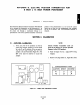
An ammeter may be connected in series for
amplifier calibration to verify position
indicating meter is giving accurate readings.
d.
With the amplifier power supply on, move power
positioner shaft to zero position. Tune zero
adjustment (as labeled on amplifier cover) until
ammeter indicates 4 mA.
e. Move the power positioner to the opposite end of
its stroke and hme the span adjustment (as
labeled on amplifier cover) for a reading of
20 mA.
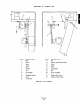
f. Replace two plug buttons (1, Figure B-2) in EPT
case.
g. Install power positioner cover and secure with
screws removed at disassembly
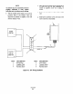
POSITION -
t
INDICATOR
(4-20
mA
AMMETER)
+
4
2
3
2 BLACK (-)
J/
WHITE (+)
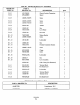
ITEM DESCRIPTION
ITEM DESCRIPTION
1 Button Plugs
5 Lock Washer
2 Amplifier Cable
6 Terminal Marker
3 Terminal Block
I Terminal Cover
4 Pan Head Screw
8 Pan Head Screw
Figure B-2. EPT Wiring Installation
IB-102-208
B-2