
Specifications
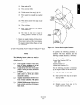
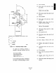
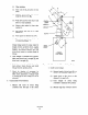
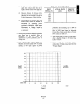
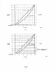
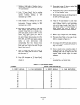
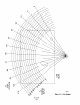
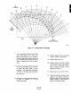


Figure A-7. Characterized Cam Example
22. Line up mounting and slotted holes of paper
cam to mounting and slotted holes of meral
cam. Cement paper cam to metal cam.
Remove material from cam as needed to
give metal cam shape of paper cam. Using
a file or similar tool, smooth curve until no
ridges or imperfections are felt on edge of
curve.
23. Install cam on power positioner and check
for a linear relationship between actual flow
of system and input signal to power
positioner. A 10% input signal will produce
a 10% flow, a 50% input signal will produce
a 50% flow. Make minor adjustments by
draw filing cam.
24. Record power positioner characterized action
in Table 4.2, schedule “D”. Use the
following procedure:
(a) Set signal air to O%,
@) Measure distance from top of packing
washer to bottom of cl&s head.
(c) Increase signal air to 10%.
(d) Measure distance from top of gland
cap to bottom of clevis head. Subtract
value in step 2. Record this value as
piston movement in inches for 10%
signal air in Table 4.2.
(e) Repeat steps (c) and (d) for 20% to
90% in 10% increments.
(f) Divide actual distance traveled at each
signal by total distance traveled to
determine percent of full stroke. Enter
percent traveled at each signal in
percent of full stroke column.