
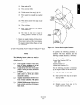
Specifications
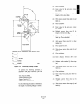


(e) Install power positioner’s drive lever so its
angle. from vatical center line (0,) is
equal to device’s driven lever angle @,).
(f) Measure distance (0) between drive
and driven levers connection holes.
Allowing for clevis length, cut pipe to
fit this meamrement. Attach clevises.
(g) Install linkage pipe between drive and
driven levers. Check for freedom of
movement by
operating power
positioner’s handwheel. Make minor
adjustments to linkage length by
turning linkage clevis fitting in or out
as necessary.
3. Checkpowerpositionercalibrationandmake
sure linear cam is installed. Refer to
paragraphs 4-2 and 4-3. Make any
adjustments to power positioner prior to
cutting cam.
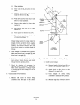
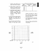
4. Copy “System Flow Chat” (Table A-l.
Measure and record actual flow of system
starting at 0% input signal to power
100
90
80
70
60
%Pu”:
SIGNAL 5o
0 /
BASE LINE
0 20 40 60 80
100
Table A-l. System Flow Chart.
INPUT ACTUAL FLOW
SIGNAL (%) (scfm)
0%
20%
40%
60%
80%
100%
PERCENT
FLOW (%)
r
1
L
positioner and increasing up to 100% in
increments of 20%. Divide actual flow by
flow at 100% input signal to determine
Percent Flow. Enter percent flow in Percent
Flow column in Table A-l.
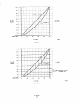
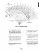
5. Near bottom edge on a sheet of graph paper,
draw a baseline (Graph 1) 10 blocks long.
Label “% Flow”.
6. Starting at left edge of baseline, draw a
vertical line 10 blocks long. Label this line
“% Input Signal”.
% CAM
ROTATION
% FLOW
Graph 1