
Specifications


(t) Clear calculator.
(u) Enter value for PI and press sine key
mv.
(v) Multiply answer from step (u) by
length of driven lever (RJ.
(w) Write down answer from step (v) and
label (v). Clear calculator.
(x) Subtract value marked (v) from value
marked (r).
(y) Add answer from step (x) to value
marked (n).
(z) Press square root function key (Jx).
(aa) The value in step (z) is equal to length
of connecting linkage “0 “.
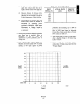
Design linkage system by using values for
lengths of drive and driven levers, angular
position of both levers from vertical
(offsets), and distance between drive and
driven levers centers to calculate length of
linkage.
5. Close damper to minimum flow position.
Make sure driven lever is at angle (PJ and
drive lever is at angle (PI).
6. Cut linkage pipe to length (0) allowing for
both clevises. Attach clevises and install
linkage between operating levers.
I. Check for freedom of movement by
operating power positioner’s handwheel.
Make minor adjustments to linkage length
by turning pipe to clevis fitting in or out as
necessary.
b. Characterized Power Positioner.
1. Measure full travel of device being
controlled from full open to full closed.
Record maximum and minimum positions.
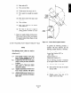
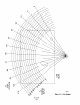
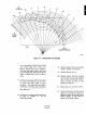
CLEVIS -1
POWER
POSITIONER
Figure A-5. Characterized Linear Linkage Design
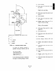
2. Install Linear Linkage.
(a) Measure length of driven lever (R,) on
device to be controlled (Figure A-5).
(b) Attach clevis to drive lever so that
distance R2 is equal to R,.
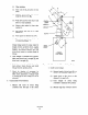
(c) Close damper of device being
controlled to minimum flow position.
(d) Measure angle (0,) of device’s driven
lever from vertical center line.