
Specifications


DRIVE
LEVER
POWER
POSITIONER
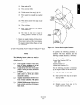
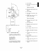
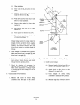
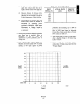
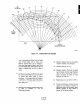
RECORD SETUP DIMENSIONS AND ANGLES USED:
PI-”
82-O
.!
_ INCHES
Rl-
INCHES
Rx-
INCHES POWll
Figure A-4. Connecting Linkage Length
To perform the following procedure, a
calculator with basic functions, plus the
following scientific functions, is necessary:
-Sine Function (SIN)
-Cosine Function (COS)
-Square Function (x2)
-Squax Root Function (Jx,
Use the following procedure to determine P,
the length of connecting linkage in inches:
(a) Clear calculator.
(b) Enter value for PI and press cosine
key (COS).
(c) Multiply answer from step (b) by
length of drive lever (R,).
(d) Write down answer from step (c) and
label (c).
(e) Clear calculator.
(f) Enter value for PI and press cosine
key (COS).
(g) Multiply answer from step (f) by
length of driven lever (RJ.
(h) Write answer from step (g) down and
label (8). Clear calculator.
(i) Add anwer from step (h) to value
marked (c).
(i) Press square key (x2)
(k) Write down answer from step (i) and
label (i).
(1) Clear calculator.
(m) Enter distance between drive and
driven shaft (L).
(n) Subtract value marked (i) from step
(“0.
(o) Write down answer from step (n) and
label (n).
(p) Clear calculator.
(q) Enter value for 0, and press sine key
(SW
(r) Multiply answer from step (q) by
length of drive lever (R,).
(s) Write down answer from step (r) and
label (r).
BlOZ-208
A-5