
Specifications


(e) Write down answer from step (d) and
label it (d). Clear calculator.
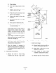
(fl Enter value for length of drive lever
W.
(g) Divide value from step (f) by value
marked (d).
(h) Press square. key (x2)
(i) Write down answer from step (h) and
label it (h) for use later.
(i) Clear calculator.
(k) Enter value for /3, and press sine key
WV.
(1) Divide answer from step (k) by 2.
(“I) Press square key (x2)
(n) Write down answer from step (m) and
label it (m) for later use.
(a) Enter value for pz and press sine key
(SW
(p) Divide answer from (o) by 2.
(4) Press square key (x2),
(I) Write down answer from (q) and label
it (q) for later use.
(s) Clear calculator.
(t) Enter value marked (h),
(u) Subtract value marked (m) from value
marked (h).
(v) Add value marked (q) to step (u).
(w) Press square root function key (Jx,.
(x) Press inverse sine @NV SW or SIN’).
(y) Write down answer from step (x) and
label it (x).
(2) Clear calculator.
(aa) Enter value for p>
(ab) Divide value from steep (aa) by 2
(ac) Write down answer from step (ab) and
label it (ab). Clear calculator.
(ad) Enter value from step (x).
(ae) Subtract value from step (ab).
(at) Multiply answer from step (ae) by 2.
(ag) The value in step (af) is equal to total
angular rotation of driven lever ‘V2”.
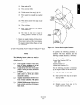
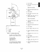
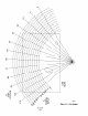
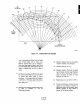
4. Figure o”t length of connecting linkage
based on length of drive lever, driven lever,
and the initial offset of both. Use Figure A-4
and the following relationship:
NOTE
The following known values are used to
calculate the length of the linkage in inches;
“Q”.
L = Length between drive and driven
shaft center lines, measured in inch-
es.
R, = Length of the drive lever (from shaft
center to clevis pin center) measured
in inches.
R2 = Length of the driven lever (from
shaft center to clevis pin center)
measured in inches.
PI = Angular measurement of drive lever
from vertical center line with piston
fully extended.
PI = Angular measurement of driven lever
from vertical center line with damper
fully closed.