
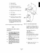
Specifications


(i) Enter value of &.
(j) Press sine key (SIN).
(k) Divide answer from step (j) by 2.0.
(1) Press square key (usually key marked
9).
(I”) Write down answer from step (1) and
label it (1).
(n) Clear calc”lator.
(o) Enter value marked (f) and subtract
value marked (l),
(p) The value in step (0) is equal to
vertical distance travelled by drive
lever “y”.
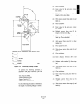
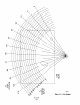
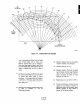
3. Figure out angular rotation of driven lever.
This is done in terms of drive lever rotation.
The. angular rotation follows Figure A-3 and
the relationship:
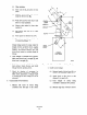
NOTE
The following known values are used to
calculate the total angular rotation of the
driven lever; Or
8, =
R, =
R2 =
PI =
P, =
Total angular rotation of the drive
lever. If power positioner is at full
stroke, this measurement is So”.
Length of the drive lever (from shaft
center to clevis pin center) measured
in inches.
Length of the driven lever (from
shaft center to clevls pin center)
measured in inches.
Angular measurement of drive lever
from vertical centerline with piston
fully extended.
Angular measurement of driven lever
from verticzd centerline with damper
fully closed.
Figure A-3. Driven Shaft Angular Rotation
To perform the following procedure, a
calculator with basic functions, plus the
following scientific functions, is necessary:
-Sine Function (SIN)
-Inverse Sine Function (SIN-I) or
-Square Function (x2)
-Square Root Function (-fx)
Use the following procedure to determine
e*, the angular rotation of the driven lever.
Add value of & to value of 8,.
Enter answer from step (a) and press
sine key (SIN).
Divide answer from step (b) by 2.0.
Multiply answer from step (c) by
length of driven lever (RJ.