
Specifications


Figure
LIST OF ILLUSTRATIONS (Continued)
Title
1.6.
8-l.
8-2.
8-3.
A-l.
A-2
A-3.
A-4.
A-S.
A-6.
A-l.
Table
l-l.
1-2.
4-l.
4-2.
4-3.
S-l.
6-l.
9-1.
9-2.
9-3.
A-l.
A-2.
Shaft Exploded View
Current to Pneumatic Converter and Regulator Replacement
Limit Switch Exploded View
Heater/Thermostat Replacement
Linear Linkage Design
Vertical Am Travel
Driven Shaft Angular Rotation
Connecting Linkage Length
Characterized Linear Linkage Design
Cam Shaping
Characterized Cam Example
LIST OF TABLES
Model Number Matrix
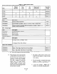
Specifications for Model PP814T Power Positioner
Device Travel (%)
Piston Travel (Stroke) Calibration Schedule
Calibration Signal Pressures
Troubleshooting Chat
Maintenance Schedule
Recommended Spare Parts for PP814T 8 x 14 Power Positioner
Spare Parts for Options (PP814T 8 x 14 Power Positioner Only)
Bill of Material for PP814T 8 x 14 Power Positioner
SystemFlowChart ..______.._...__.___......____
Cam Rotation Points
.........
.........
.........
.........
.........
.........
.........
.........
.........
.........
.......
.......
.......
.......
.......
.......
.......
.......
.......
.......
.......
.......
Page
7-11
8-O
8-3
8-S
A-l
A-2
A-3
A-S
A-6
A-10
A-11
Page
1-2
1-s
4-2
4-3
4-s
s-1
6-1
9-l
9-2
9-3
A-l
A-9