
Specifications


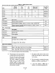

TABLE OF CONTENTS (Continued)
SlXtiOIl
Page
VIII. OPTIONS .., .., __ ___ ._ .., __
8-l. Overview
8-2. Electric Position Transmitter
8-3.
Current to Pneumatic (I&‘) Converter and Regulator
8-4.
Lit Switch
8-5. HeatWTbennostat
.......................
.......................
.......................
.......................
.......................
.......................
8-l
8-l
8-l
8-l
8-2
8-4
IX. RECOMMENDED SPARE PARTS 9-l
X. RETURNING EQUIPMENT TO THE FACTORY
APPENDIX A. LINKAGE INSTALLATION FOR EITHER A CHARACTERIZED
FLOW CONTROL DEVICE, OR A LINEAR FLOW CONTROL DEVICE
APPENIDX B. ELECTRIC POSITION TRANSMITTER FOR 8 INCH X 14 INCH
POWER POSITIONER
INDEX ._.._.__.____..____..._.___.........................___.._...__.
LIST OF ILLUSTRATIONS
Figure
Title
l-l.
l-2.
l-3.
2-1.
2-2.
2-3.
2-4.
2-5.
3-l.
4-l.
4-2.
4-3.
4-4.
4-5.
6-l.
6-2.
6-3.
6-4.
6-5.
6-6.
6-7.
7-l.
7-2.
l-3.
7-4.
7-5.
Typical System Package
Power Positioner Operation
Typical Power Positioner Installation
Clearance Requirements
Mounting Dimensions
Power Positioner Torque Chat
Air Piping Schematic
Angular Relationship of Drive and Driven Arms
Reverse Operation
Calibration Flowchart
Stroke Adjustment
Current to Pneumatic converter
Linear Linkage Calibration
Characterized Linkage. Calibration
Lubrication Chat
Pilot Valve Exploded View
Diaphragm Exploded View
Air Lock Diaphragm
Exhaust Blocking Valve
Cylinder Exploded View
Mechanical Linkage
Pilot Valve Exploded View
Air Filter
Receiver Exploded View
Air Lock Diaphragm
Cylinder Exploded View
10-l
A-l
B-l
I-l
Page
l-l
l-3
l-4
2-2
2-2
2-3
2-4
2-5
3-l
4-l
4-4
4-5
4-6
4-6
6-2
6-3
6-5
6-6
6-7
6-9
6-11
l-2
7-3
l-4
7-6
7-8