
Specifications

h. Shaft Bush&. Use the following procedure to
replace shaft bushings.
1. Remove power positioner from service. Set
signal air to zero.
2. Move transfer valve to automatic position
and prop air lock clapper lever open.
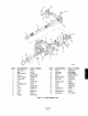
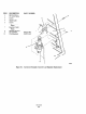
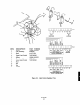
3. Remove screws (7, Figure 7-6) securing
sector gear (6) and remove sector and key
(8) from shaft (2).
4. Remove screws (11) securing cylinder lever
(9) and remove cylinder lever and key (10)
from shaft.
5. Remove screw (24) securing linkage lever
(23) and remove linkage lever from shaft.
6. Remove screws (13) securing cam mounting
bracket (12) and remove cam mounting
bracket from shaft.
7. Remove screws (19) securing limit switch
cam shoes (17) from cam caps (18) and
remove cams from shaft.
8. Pulling one end of shaft (2), remove shaft
from bushing blocks and remove spacer (4).
9. Remove grease fitting (5) from bushing
block.
10. Break Loctite seal by pounding on shaft
bushing (3). Remove shaft bushing from
bushing block.
NOTE
Bushings are secured to stand assembly with
a coating of Loctite applied to the outside of
bushings. Insertion of new bushings and
complete b~~taUation of shaft assembly must
be completed before Lo&e sets. This is
needed to line up bushings properly. The
Loctite will set in approximately 3 minutes.
Complete instzdlation of shaft assembly
within 15 minutes from when adhesive was
applied.
11. Apply Loctite primer (llNA7901A30), to
outside surface of shaft bushing (3) and
allow primer to set for three to five minutes.
12. After primer has set 3 to 5 minutes, apply
Loctite adhesive #680 and slide shaft
bushing (3) in bushing block within three
minutes.
13. Insert shaft (2) through both bushing blocks
to align bushings.
14. Allow Loctite to set for 15 minutes. Remove
shaft (2) and drill 506 inch hole into new
shaft bushing (3) through bushing block.
15. Insert shaft (2) through both bushing blocks
and spacer (4) as shown in Figure 7-6.