
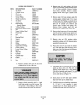
Specifications

ITEM
1
2
3
4
5
6
7
8
9
10
11
12
13
14
15
16
17
18
19
20
21
22
23
24
25
26
27
28
29
30
31
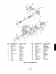
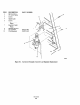
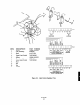
LEGEND FOR FIGURE 7-5
DESCRIPTION PART NUMBER
set screw 120083-021
Cylinder Lever 342375
Clevis 242370
Clevis Pin
146009
Grease Fitting
139656-001
Gland Cap Screws 120093.023
set Screw
120083-022
Gland Cap 142367
Rod Packing 2831A92HOl
Female Adapter
V-Ring Packing 2831A94HOl
Rod Packing Male Adapter 2831A93HOl
Nut
120032-012
Upper Cylinder Head 242407
Piston Rod 242369
Nut 120032-012
Washer 120114-008
Bearing Block 142645
screws 120088-125
Gasket 141279
Elbow 120017-020
Cylinder Connector 250891
Upper Piston O-Ring
120039.016
Piston Follower 342371
Lower Piston O-Ring 120039.032
Piston 241282
Stop Nut 129074.006
Cylinder 242405
Cylinder Stud 243252
Gasket 141279
Lower Cylinder Head 342372
Nut 120032-012
6. Remove cylinder clevis pin (4) and move
cylinder lever (2) out of the way.
7. Support cylinder assembly with 2 x 4 inch
board long enough to provide leverage. This
will prevent it from falling to floor when
cylinder bearing block nuts are removed.
8
9,
10.
11.
12.
Remove nuts (15) and washers (16) from
screws (18) securing cylinder bearing blocks
(17) to frame assembly. Remove cylinder
from frame assembly. Remove cylinder
bearing blocks from upper cylinder head
(13).
Remove nuts (12) from cylinder studs (28)
securing upper cylinder head (13) to lower
cylinder head (30). Pulling on cylinder clevis
(3), pull piston assembly and upper cylinder
head o”t of cylinder (27). Remove and
discard upper cylinder bead gasket (19).
Remove lower cylinder head (30) and
discard lower cylinder head gasket (29).
Remove gland cap screws (6) securing gland
cap (8) and move gland cap up piston rod.
Remove and discard old rod packings (9, 10
and 11).
Remove stop nut (26) securing piston
assembly to piston rod (14). Remove piston
assembly from piston rod.
Wipe piston rod (14) and inside of cylinder
(27) with clean shop cloth and spray with a
light coat of dry film lubricant (molybdenum
disulfide spray lubricant).
13.
14.
15.
Place gland cap (8) over piston rod so top of
gland cap faces cl&s (3). Pack new rod
packing female adapter (9), V-ring packing
(10) and rod packing male adapter (11) with
MoS,-793 and carefully place over piston
rod in order shown in Figure 7-5.
Insert piston rod (14) into upper cylinder
head (13) from top of cylinder head.
Carefully press new rod packing components
(9, 10 and 11) into opening in upper
cylinder head (13). Secure gland cap (8) to
cylinder head with gland cap screws (6).