
Specifications
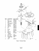

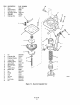
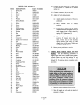
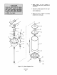

ITEM DESCRIPTION
PART NUMBER
1 Spring Nut
140903
2 Nut
120036-003
3
Washer 120197.003
4
SCEW
174306
5
Nut 120032-010
6 Washer 120114-007
7
Spring Bracket 242647
8 Seal 141173-010
9 screw 120093.058
10
screw 120094-012
11
SW%
120088-003
12 Valve. Bracket 141176.003
13 Transfer Valve 141187
14 Washer 120110-006
15 Nut 120032-005
16 Adapter 120020-007
17
Elbow 120117-003
18 Co”“ector
125368.009
19 Supply Aii Co”“ector 252588
20 Tee 120019-015
21 Co”“ector
125368.007
22 Diaphragm Chamber 342376
23 Bearing 141168-008
24
SW34
120090.079
25 Nut 120036-002
26 Plug 120042-002
27 Wotm Guide 142646
28 Stud 141168-006
29 Stud 141168-005
30 Diaphragm 9351-003
31 Shield 141168-004
32 Coupling 141168-003
33 Diaphragm Plate 242406
34
SIXU
120088-031
35 set screw 120083.014
36 Spring Co”“ector 140904
37 Nut 120036-002
38 Nut 120033-002
39
SC”%
140905
40 Clapper Lever 357720
41
SC*eW
120088.084
42 Washer 1200197.010
43 Stop Bolt 120090-052
44 Pivot Pin 157704
45 SCEW 120088-034
46
SC*.%
120088-036
47 Spring 140895
48 Worm Shaft 341156.001
49
Sc*WJ
120088-056
50 Nut 120032-008
51 Nut 120032-008
52 Co”nector 252592
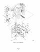
LEGEND FOR FIGURE l-4
18.
19.
20.
21.
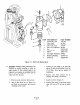
Connect air lock spring nut (1) with screw
(4) and washer (3). Tighten nut (2) against
spring nut.
Connect connector (18) to tee (20).
Adjust air lock spring tension.
(a)
(b)
(cl
(4
Apply supply air pressure of 30 psi to
positioner.
Move transfer valve to manual
position.
Loosen nut (2, Figure 7-4) by turning
counterclockwise and tighten screw (4)
until clapper lever is held closed by
spring (47). Tighten nut (2).
Move transfer valve to automatic
position. If clapper lever does not
open, loosen nut (2) and decrease
spring tension with screw (4) until
clapper lever is fully open. Tighten ““t
(2) against spring nut (1).
Return power positioner to service.
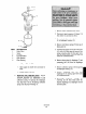
e. Cylinder Head Gaskets. Piston and Rod
paeking. Use the following procedures to
replace upper and lower cylinder head gaskets,
cylinder piston cup and rod packing. If not
replacing piston and rod packing, skip steps 10
through 16. If replacing piston, complete entire
procedure.
1. Remove power positioner from service.
2. Shut off supply air valve and set signal air
pressure to 0 psig.