
Specifications
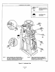
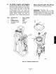
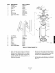

1. Place gland cap (6) onto upper cylinder head (9)
and secure with screws (5).
m. Wipe piston rod (15) with a clean shop towel and
apply a light coating of McLube MoS,-793.
n. Pack concave area of piston with McLube
MoS,-793.
o. With a clean shop towel and commercial dry
cleaning solvent, wipe interior surface of cylinder
(17). Inspect cylinder for cracks or scoring.
Replace cylinder if it appears damaged. Refer to
Section VII for replacement procedures. Allow to
air dry completely before reassembling cylinder.
p.
Install upper cylinder head (9) and piston assem-
bly into cylinder (17) with new cylinder gasket
(14). Secure upper cylinder head to lower cylin-
der head (19) with cylinder studs (18) and nuts
(7).
q.
Place bearing blocks (12) on upper cylinder head
(9). Place cylinder assembly in frame assembly
onto 2 x 4 inch board for support. Secure bearing
blocks to frame assembly with screws (13), lock
washers (11) and nuts (10). Remove 2 x 4 inch
board.
r.
Insert end of cylinder lever (2) into slot of clevis
(4).
s.
Align holes in clevis (4) with hole in cylinder
lever (2) and drive clevis pin (3) in securing
clevis to cylinder lever. Secure clevis pin with set
screw (1).
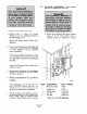
t. Open supply air valve and test for air leakage
around cylinder head. Use a leak detector, such
as “Snoop”, and send an air signal to power
positioner. If leak is detected, repair as necessaq.
u. Using grease gun filled with MoS,-793, lubricate
clevis and bearing blocks.
v. Calibrate power positioner stroke; refer to Section
IV. Return power positioner to service.
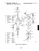
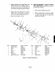
6-10. MECHANICAL LINKAGE SYSTEM
CLEANING AND INSPECTION. Clean power
positioner mechanical linkage of all grease buildup
and inspect for damage and wear every two years.
Refer to Figure 6-7 and use the following procedure.
a. Remove power positioner from service.
b. Shut off supply air valve
c. Clean all grease off of handwheel sprocket (18)
and worm sprocket (2). Inspect sprockets for
damage or missing teeth.
d. Wipe old grease from chain (14) and inspect
chain for damaged links.
e. Ensure handwheel shaft block (22) and worm
shaft blocks (5) are tight and secure.
f. Rotate handwheel (16) and inspect worm shaft
(9) for damage.
g. Lubricate worm shaft block (4) and handwheel
shaft block (22) with grease gun filled with
MoS,-793. Wipe chain (14) with MoS,-793.