
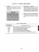
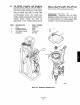
Specifications
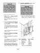

c. Remove link nut (18) from exhaust valve link (9)
and remove exhaust valve link.
d. Remove screws (12) securing exhaust blocking
valve assembly from frame and remove exhaust
blocking valve assembly.
e. Remove four screws (11 and 16) and nuts (3)
from exhaust blocking valve assembly. Remove
end cover (4) from exhaust valve body (8).
f. Remove gasket (5) and discard. Remove thrust
plate (7) and spring (6). Inspect contact surfaces
of exhaust valve body (8) and thrust plate for
pitting and wear. Replace as required.
g. Using a sharp putty knife, prepare gasket surfaces
on end cover and exhaust valve body by remov-
ing any old gasket material or dirt.
h. Place new gasket (5) on end cover (4). Install
spring (6) and thrust plate (7).
i. Assemble end cover (4) with exhaust valve body
(8) and install screws (11 and 16) and nuts (3).
j. Mount exhaust blocking valve assembly in frame
and install screws (12).
k. Install exhaust valve link (9) through diaphragm
base and clapper lever. Replace link nut (18) on
exhaust valve link only enough to keep it in
place.
1. Reattach exhaust connector (1) to exhaust valve
assembly.
m. Adjust exhaust valve link nut (18).
1. Move transfer valve to automatic position so
clapper lever opens and prop clapper lever
Opl.
2. Draw exhaust valve link nut (18) onto ex-
haust valve link (9) until it comes into
contact with clapper lever.
3. Carefully move valve lever (14) toward
frame to open exhaust valve. Holding valve
lever in open position, gently tighten link
nut (18) against clapper lever.
4. Remove prop from clapper lever.
n. Restore signal air pressure and return power
positioner to service.
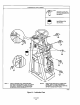
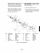
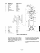
6-9. CYLINDER AND PISTON, CLEANING AND
INSPECTION. Disassemble, clean and lubricate
piston and cylinder assembly approximately every two
years. Refer to Figure 6-6 and use the following
p*OCdU*e.
a.
b.
c.
d.
e.
f.
g.
h.
Remove power positioner from service.
Shut supply air valve and set signal air pressure
to 0 psig. Set transfer valve on top of machine to
manual.
Loosen cylinder upper hose and cylinder lower
hose to bleed residual air from cylinder.
Remove cylinder upper hose from upper cylinder
head and cylinder lower hose from lower cylinder
head.
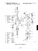
Remove cylinder clevis pin set screw (1) and
cylinder clevis pin (3). Disconnect cylinder lever
(2) from cylinder clevis (4).
Support cylinder assembly with 2 x 4 inch board
long enough to provide leverage. This will
prevent cylinder from falling to floor when
cylinder support nuts (10) are removed from
bearing block (12) and frame.
Remove nuts (10) and lock washers (11) from
screws (13) securing bearing blocks (12) to frame
assembly. Remove cylinder from frame assembly.
Remove bearing blocks from cylinder head.
Remove nuts (7) from studs (18) securing upper
cylinder head (9) to lower cylinder head (19).
Full piston assembly and cylinder head out of
cylinder assembly. Remove and discard upper
cylinder gasket (14).