
Specifications
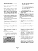

b. Measure clearance between worm shaft (2) and
worm gear sector (1). Clearance should be
between l/8 to 3116 inch. If clearance is not in
this range, loosen lock nut (5) and adjust stop
bolt (6) until worm shaft to gear sector clearance
is between l/X and 3/16 inch. Tighten lock nut.
c. Remove prop from clapper lever (3). Move
transfer valve to manual position and check to
ensure worm shaft (2) engages gear sector (1).
d. Return power positioner to service.
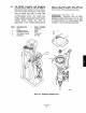
6-8. EXHAUST BLOCKING VALVE CLEANING
AND INSPECTION. Disassemble, clean and
inspect exhaust blocking valve every two years, or
upon indication of leakage.
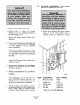
a. Remove power positioner from service.
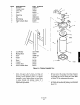
b. Release residual exhaust air pressure by pulling
on exhaust valve link nut (18, Figure 6-5).
Disconnect exhaust connector (1) from exhaust
blocking valve assembly.
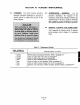
ITEM DESCRIPTION PART NUMBER
1 Exhaust Tubing 252592
2 Adapter 120020.007
3 Nut 120033-006
4
End Cover 2831A30HOl
5 Gasket 142674
6
spring
140914
I Thrust Plate
142675
8 Exhaust Valve Body 2831A29HOl
9 Link 141181.005
ITEM DESCRIPTION PART NUMBER
10 Studscrew 142617
11
SC”%’
120093-090
12
SCEW
120088-004
13
Pin 141181-002
14
Valve Lever
141181-003
15 Nut 120033-002
16
SCEW
120093.092
17 Fulcrum Block 142676
18 Link Nut
120033-002
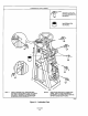
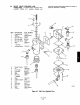
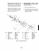
F&we 6-5. Exhaust Blocking Valve