
Specifications

a. Remove power positioner from service.
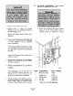
b. Remove screws (1, Figure 6-3) securing
diaphragm cover (‘2) to diaphragm housing (3).
Remove diaphragm cover.
c. Remove zero balance spring (4) from top of
diaphragm.
d. Using a clean, damp shop towel, thoroughly wipe
off any dirt or debris on upper side of diaphragm
(5). Allow diaphragm to air dry completely
before reassembling.
e. Visually inspect diaphragm (5). Replace if nicks,
cuts, or hardened rubber areas (from excess heat)
are visible. Refer to Section VII for replacement
procedures.
f. Clean diaphragm cover (2) and zero balance
spring (4) with commercial dry cleaning solvent
and allow to air dry.
g. Align the edges of diaphragm (5) with diaphragm
housing (3) to make an air tight seal. Replace
zero balance spring (4).
h. Making sure the diaphragm (5) is not folded or
pinched, replace diaphragm cover (2) on top of
diaphragm.
i. Secure diaphragm cover (2) with screws (1).
Snug up all saws evenly then tighten in a criss
cross pattern. Make. sure. all screws are tightened
equally to prevent distortion of diaphragm.
j. Test for air leakage sound diaphragm cover (2)
and diaphragm housing (3). Using a leak detector,
such as “Snoop”, apply an air signal to power
positioner. If leak is detected, repair as necessary.
6-7. AIR LOCK ADJUSTMENT. Use the following
procedure for adjustment of the air lock.
a. Remove power positioner from service. Reduce
signal air to 0%. Move transfer valve to
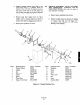
automatic position so clapper lever (3, Figure
6-4) opens. Prop clapper lever open.
3
6
I
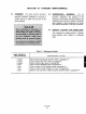
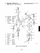
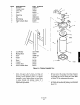
ITEM DESCRIPTION PART NUMBER
1 Worm Gear Sector 341183
2 Worm Shaft 341156-001
3 Clapper Lever
357720
4 Shaft Bearing 141168-008
5 Lock Nut 120036-002
6 Stop Bolt
120090-052
Figure 6-4. Air Lock Diaphragm