
Specifications
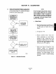
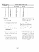
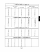
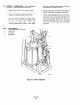
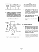
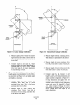
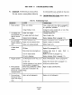


Figure 4-4. Linear Linkage Calibration
2. Measure angle 8, from vertical line extend-
ing from device lever hub, to driven lever of
device being controlled. Tbis is the driven
lever offset.
3. Compare angle !3, and angle &. Adjust
length of linkage for minor adjustments by
threading pipe in or out of clevis. Change
drive lever angle PI for major adjustments
by repositioning on shaft.
b. Characterized. Verify linkage design angles and
length against actual installation. Use the follow-
ing procedure and Figure 4-5, and adjust angles
and lengths as necessary.
1. Measure angle p, from vertical line
extending from shaft hub to power
positioner drive lever. This is the power
positioner drive lever offset.
2. Measure angle b2 from vertical line
extending from device lever hub to
drivenlever of device being controlled. This
is the driven lever offset.
POWER
POSITIONER
L-
Figure 4-5. Characterized Lbkage Calibration
3. Measure length between connecting levers.
This distance is represented by the letter 8.
4. Measure length of power positioner drive
lever (R,) from shaft to center of clevis pin.
5. Measure lengtb of device driven lever (RJ
from shaft center to center of clevis pin.
6. Compare angle PI, p2, distance 0, and
length R, and Rz with setup dimensions and
angles recorded in Appendix A, Figure A-4.
If setup dimensions and angles were not
recorded, use formulas in Section II to
calculate correct design for the positioning
system and record in Appendix A, Figure
A-4. Adjust length of linkage for minor
adjustments by threading pipe in or out of
cl&s. Change drive lever angle fi, for
major adjustments.
l&to*-208
‘l-6