
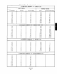
Specifications


4-2. STROKE CALIBRATION. Use the following nut slowly clockwise until piston rod moves to
procedures to adjust power positioner stroke.
lowest position. Tighten set screw.
a.
b,
c.
Purge air lines to remove any water or debris.
Move transfer valve to automatic position and set
signal air to minimum stroke position (0%).
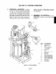
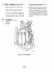
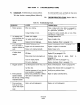
Loosen set screw (3, Figure 4-2) holding spring
nllt (2)
in place. TUXl spring nut
counterclockwise until piston rod (4) begins
moving up from bottom of stroke. Turn spring
ITEM DESCRIPTION
1 Stroke Adjustment I
2 Spring Nut
3 Set screw
4
Piston Rod
5
CEUII
d.
e.
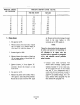
Increase signal air to maximum (100%). Refer to
Table 4-3 for percent to signal air conversion.
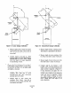
Loosen stroke adjustment lock screw (1). Move
loose end of cam toward shaft until piston rod
(4) moves downward. Slowly move cam away
from shaft until piston rod moves to maximum
position or to desired length of travel. Tighten
lock screw.
Figure 4-2. Stroke Adjustment