
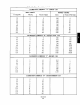
Specifications


a. Reverse Com~ematine
Assembly.
1. Remove power positioner from service.
2. Close the supply air valve
3. Set signal air to 0.
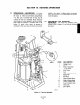
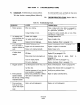
4. Remove pivot screw (4) and stroke adjust-
ment lock screw (3) securing cam (5) to cam
mounting bracket (6) and remove cam.
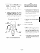
5. Invert cam as shown in Figure 3-1, View A.
Install pivot screw (4) and stroke adjustment
lock screw (3) through cam into cam mount-
ing bracket.
b. Exckanae Cvlinder Hoses.
1. Tag and remove upper cylinder hose (9) and
lower cylinder hose (11) from cylinder
heads.
2. Install upper cylinder hose into lower cylin-
der head (12). Install lower cylinder hose.
into upper cylinder head (10).
c. Calibrate Stroke.
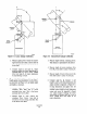
1. Disconnect linkage lever (1, Figure 3-l) at
clevis (2) from device being controlled.
2. Open supply air valve. This will cause
piston rod (15) to move to top of its stroke.
Set signal air to minimum.
3. Using an allen wrench loosen set screw (8)
holding spring nut (7).
4. Turn spring nut counterclockwise until
piston rod (1.5) starts to move downward.
5. Turn spring nut (7) slowly clockwise. until
piston rod reaches maximum position.
6. Tighten set screw (8) to hold spring nut
fdy in place.
7. Set signal air to maximum amount and
check movement of piston rod (15) for full
stroke. The piston rod should just reach
bottom of stroke with maximum signal to
pilot valve. If necessary, loosen stroke ad-
justment lock screw (3) and move cam (5)
away from shaft until full stroke is reached.
8. Reconnect linkage lever (1) at cl&s (2) to
device being controlled.