HAGAN POWER POSITIONER TORQUE TYPE 8x14 Instmction Bulletin IB-102-208 Rev. 1 ROSEMOUNT”ANALYTICAL FISHER.
ROSEMOUNT WARRANTY Rosemount warrants that the equipment manufactured and sold by it will, upon shipment, be free of defects in workmanship or material. Should any failure to conform to this warranty become apparent during a period of one year after date of shipment, Rosemount shall, upon prompt written notice from the purchaser, correct such nonconformity by repair or replacement, F.O.B. factory of the defective part or pats.
PURPOSE The purpose. of this manual is to provide a comprehensive understanding of the Hagan 8 x 14 Power Positioner, components, functions, installation, and maintenance. This manual is designed to provide information about the Hagan 8 x 14 Power Positioner. We recommend that you thoroughly familiarize yourself with the Description and Installation sections before installing your power positioner.
TABLE OF CONTENTS Page Rosemount Warranty .......................................... Purpose ................................................... I. ............ ............ i ii DESCRIPTION .................................... 1-1. Component Checklist of Typical System ............... 1-2. Model Number Matrix ........................... 1-3. System Overview ............................... 1-4. Model PP814T Specifications ....................... 1.5. Storage Instructions .............................
TABLE OF CONTENTS (Continued) SlXtiOIl Page VIII. OPTIONS .., .., __ ___ ._ .., __ 8-l. Overview 8-2. Electric Position Transmitter Current to Pneumatic (I&‘) Converter and Regulator 8-3. Lit Switch 8-4. 8-5. HeatWTbennostat IX. RECOMMENDED X. RETURNING APPENDIX APPENIDX INDEX SPARE EQUIPMENT 8-l 8-l 8-l 8-l 8-2 8-4 PARTS 9-l TO THE B. ELECTRIC POSITION POWER POSITIONER 10-l FACTORY A.
LIST OF ILLUSTRATIONS Figure 1.6. 8-l. 8-2. 8-3. A-l. A-2 A-3. A-4. A-S. A-6. A-l. (Continued) Title Shaft Exploded View Current to Pneumatic Converter and Regulator Replacement Limit Switch Exploded View Heater/Thermostat Replacement Linear Linkage Design Vertical Am Travel Driven Shaft Angular Rotation Connecting Linkage Length Characterized Linear Linkage Design Cam Shaping Characterized Cam Example LIST Page 7-11 8-O 8-3 8-S A-l A-2 A-3 A-S A-6 A-10 A-11 ......... ......... ......... ......... ..
SECTION l-l. I. DESCRIPTION COMPONENT CHECKLIST OF TYPICAL SYSTEM. A typical Rosemount 8 x 14 Power Positioner package should contain the items shown in Figure l-l 1-3. SYSTEM OVERVIEW. a. w. This Instruction Bulletin has been designed to supply details needed to install, operate, and service the Rosemount 8 x 14 Torque Type Power Positioner (Figure l-l).
Includes air filter style 372538-Z and Cl&s, Table l-l. Model Number style 274472 Mallual Operator Code Dust COVW 452167 X 457696 X I x I Air Lock Heater and Thermostat Shp Wgt Ibs/kgs 850/385,9 X I x 443700 X X X 457031 X X X Code Matrix.
c. Operational Description. The Model PP814T Torque Type Power Positioner is a pneumatic driven, double acting piston type power cylinder in which the linkage lever is positioned to a specific setting for each input signal. The power positioner is mounted on a steel floor stand. The unit is covered and protected by a splash proof metal dust cover. The power positioner is used to position devices such as inlet vanes, control valves, and dampers.
The upward movement of the piston rod moves the cam downward. This causes the follower arm, riding on the cam, to lift the spring nut, increasing pressure on the calibration spring. This increased pressure on the calibration spring returns the diaphragm to its neutral position, closing the pilot valve air ports. Without additional air pressure, piston movement is stopped. As signal air decreases the calibration spring pressure moves the diaphragm up.
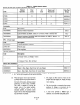
Table 1-2. Specitlcations Signal Requirements Inputs: 4.20 mA/3-15 psigB30 for Model PPS14T Power Positioner. psig PWfOl?%BKX Repeatability ................................ Full Stroke Time (unloaded) ...................... Maximum Cylinder Air Pressure Supply Air Consumption ........................ ControlTorque ............................... Maximum Friction Load ........................ Stall Torque ................................. outputs ....................................
c. Storaee Preventive Maintenance. If storing power positioner longer than six months, observe the following preventive maintenance guidelines. 1. Cycle cylinder and piston either manually or by air every six months. 2. Perform General Cleaning and Lubrication (paragraph 6.3), and Cylinder and Piston, Cleaning and Lubrication (paragraph 6.9), before installing power positioner.
SECTION 2-1. 2-2. II. INSTALLATION OVERVIEW. The power positioner is designed to be installed upright. The floor stand is bolted to a prepared horizontal foundation. A minimum of 45 psig to a maximum of 120 psig supply air pressure is needed at mounting location. The power positioner must be controlled by either a” electrical signal, when “sing a” I/P signal converter, or by a” air signal. All wiring must conform to local and national codes. which flow changes per valve position is increawl.
NOTE: DIMENSIONS ARE IN INCHES. 1 50.5c, PI @=il 7 0 - I Figure 2-l. Clearance Requirements c. Mounting Procedure. 1. Design and Manufacture Foundation. Foundation must be able to withstand at least 1670 ft-lbs torque plus 900 lbs weight. Refer to Figure 2-2 for footprint dimensions of power positioner. Use this footprint as a guide to design foundation to match baseof power positioner. Mounting holesin baseare drilled for 3/4 inch foundation bolts.
0 1000 2000 MAXIMUM 3000 TORQUE 4000 REQUIRED 5000 6000 (FT-LBS) PC0006 Figure 2-3. Power Positioner 2-4. AIR SUPPLY INSTALLATION. Using Figure 2.3, match the torque load needed to position your device to the “maximum torque required” axis along the bottom of the graph. From this point, move vertically up to the control torque curve. From the point that intersects control torque curve, move. horizontally to the left scale labeled “supply air pressure”.
t PRESSURE REGULATORJFILTER T -/ ’ TO DIAPHRAGM l/4 INCH NPT FEMALE CONNECTION AIR CONNECTION MANIFOLD /i 2~~ --- SUPPLY AIR >I00 PSIG SHUTOFF TO PILOT VALVE VALVE AIR FILTER VIEW A POWER POSITIONER WITH CURRENT TO PNEUMATIC SIGNAL CONVERTER (l/P) 15 FEET MAXIMUM t-----L OR 3-.-15 PSIG -.-..
2-6. LINKAGE INSTALLATION. I” a “mnal installation, most customers install the linkage with both the drive Amy and damper driven arm positioned so that both anns establish a” approximate right angle (90”) to the drive line at mid range of travel as illustrated in Figure 2-5. For more detailed information on linkage arrangement and options refer to Appendix A LINKAGE INSTALLATION FOR EITHER A CHARACTERIZED FLOW CONTROL DEVICE, OR A LINEAR FLOW CONTROL DEVICE. I DRIVEN - LINKAGE DRIVE Figure 2-5.
SECTION 3-1. III. REVERSE OPERATIONAL DESCRIPTION. In reverse acting positioners, the piston and piston rod operate. the same as when set up for direct acting (Figure l-2). The cam is reversed front to back and the cylinder air hoses are exchanged. These alterations cause supply air to be directed to the top of piston when signal air pressure is increased and to the bottom of piston when signal air pressure is decreased. In this case, piston movement is inversely OPERATION related to the signal.
a. Reverse Assembly. Com~ematine c. Calibrate Stroke. 1. Disconnect linkage lever (1, Figure 3-l) at clevis (2) from device being controlled. 1. Remove power positioner from service. 2. Open supply air valve. This will cause piston rod (15) to move to top of its stroke. Set signal air to minimum. 2. Close the supply air valve 3. Set signal air to 0. 4. Remove pivot screw (4) and stroke adjustment lock screw (3) securing cam (5) to cam mounting bracket (6) and remove cam. 5.
SECTION 4 -1. IV. CALIBRATION CHECK POWER POSITIONER CALIBRATION. Use the following procedure to check calibration of power positioner. Figure 4-1, Calibration Flowchart is provided as a quick reference guide. IS PERCENTAGE OF TRAVEL OF DEVICE EQUAL TO CORRESPONDING PERCENTAGE OF NOTE If cam was shaped (characterized), values of percent output desired must be recorded upon instalIation in Table 4-1, Schedule D. This is necessary to check calibration.
Table 4-1. Device Travel (%). PERCENT SIGNAL AIR PRESSURE 0 10 20 30 40 50 60 70 80 90 100 b. l- PERCENT DRIVEN LEVER LINEAR SQUARE ROOT CJX) SQUARE cx’, 0 10 20 30 40 50 60 70 80 90 100 0.0 31.6 44.8 54.8 63.25 70.7 77.5 83.7 89.4 94.9 100.0 0.0 1.0 4.0 9.0 16.0 25.0 36.0 49.0 64.0 81.0 100.0 Piston Travel. 1. Set signal air to 0% 2. Measure distance from top surface of gland cap (13, Figure 3-1) to bottom surface of clevis head (14). Label this distance “A”. 3. Increase signal to 100%. 4.
Table 4-2. Piston CALIBRATION INPUT 3-15 psig (UP) 3.0 4.2 5.4 6.6 7.8 9.0 10.2 11.4 12.4 13.8 15.0 ! I Calibration “A” CALIBRATION - LINEAR CAM Inches 0 10 20 30 40 50 60 70 80 90 100 SCHEDULE 0.00 1.40 2.80 4.20 5.60 7.00 8.40 9.80 11.20 12.60 14.00 “B” - SQUARE ROOT 0 IO 20 30 40 50 60 70 80 90 100 SCHEDULE “C” - SQUARE “D” 0 10 20 30 40 50 60 70 80 90 100 I%10%208 4.3 I I Percent of Full Stroke 0 10 20 30 40 50 60 70 80 90 100 0.0 31.6 44.8 54.8 62.25 70.70 77.50 83.70 89.40 94.
4-2. STROKE CALIBRATION. Use the following procedures to adjust power positioner stroke. a. Purge air lines to remove any water or debris. b, Move transfer valve to automatic position and set signal air to minimum stroke position (0%). c. ITEM 1 2 3 4 5 Loosen set screw (3, Figure 4-2) holding spring nllt (2) in place. TUXl spring nut counterclockwise until piston rod (4) begins moving up from bottom of stroke.
Table 4-3. Calibration SIGNAL STROKE POSITION 4-3. Make power rating signal AIR 3-15 psig (I/P) O-30 psig 3 15 0 30 0% 100% NOTE Signal Pressures. CURRENT TO PNEUMATIC (I/P) SIGNAL CONVERTER CALIBRATION. Calibrate current to pneumatic signal converter after mounting, changing mounted position, or when loss of control is noticed (refer to Section V, Troubleshooting). Use the following procedures to calibrate the signal converter: a.
LPOWER POSITIONER Figure 4-4. Linear Linkage Calibration Figure 4-5. Characterized 2. Measure angle 8, from vertical line extending from device lever hub, to driven lever of device being controlled. Tbis is the driven lever offset. 3. Compare angle !3, and angle &. Adjust length of linkage for minor adjustments by threading pipe in or out of clevis. Change drive lever angle PI for major adjustments by repositioning on shaft. b. Characterized.
SECTION 5-l. V. TROUBLESHOOTING OVERVIEW. Troubleshooting of common problems is provided for in troubleshooting chart (Table 5-l). The chart describes common problems, followed by the related probable cause, and finally by what action is necessary to correct the defect. 5-2. Table 5-1. Troubleshootim TROUBLJZSHOOTTNG CHART. Refer to Table 5-l. Chart. PROBLEM CAUSE CORRECTION 1. Erratic operation Pilot valve sticking. Clean or replace pilot valve.
SECTION 6-1. VI. PERIODIC OVERVIEW. This section describes preventive maintenance for the Rosemount Model PP814T Power Positioner. Preventive maintenance is necessary at specific intervals to reduce wear and tear on the power positioner. 6-2. MAINTENANCE SCHEDULE. Use the maintenance schedule, Table 6-1, as a guideline for preventive mai”tenance. The frequency of this maintenance varies directly with plant conditions and operational load on the power positioner.
LUBRICATION 1 CHART GREASE GUN WITH McLUBE SEE NOTE McLUBE SEE NOTE NOTE 1: USING A GREASE GUN, LUBRICATE ZERK FITINGS AT PISTON ROD CLEVIS, FOLLOWER ARM, SHAFT ASSEMBLY, BUSHING BLOCKS, HANDWHEEL SHAFT BLOCK, WORM SHAFT BLOCK AND BEARING BLOCKS. Figure 6-1. Lubrication NOTE 2: Chart FILLED M&,-793 1. M&,-793 2. WlPE PISTON ROD WITH A CLEAN SHOP TOWEL. APPLY A LIGHT COATING OF McLUBE M&-793. WIPE EXCESS GREASE OFF WITH CLEAN SHOP TOWEL.
6-4. PlLOT VALVE CLEANING AND INSPECTION. In normal service, the pilot valve assembly (Figure 6-2) requires cleaning and inspection at intervals of appmimately upon any indication of sticking. 26 120017-019 120103-1632175 252590 Figure 6-2.
h. Remove power positioner from service. Carefully hold upper end of pilot (4, Figure 6-2) with a 506 inch wrench. Free connecting link (1) from stem by turning connecting link lower nut counterclockwise. valve stem open end pilot valve ball socket Disconnect air supply tubing (8) from elbow (7). Disconnect exhaust connector (11) from tube connector (10). Remove nuts (12) and lock washers (13) that secure pilot valve to threaded studs (15) on pilot valve manifold (17).
6-5. ITEM 1 2 3 4 5 AIR FILTER CLEANING AND DRAINING. I” nornml service, supply air filter and signal air filter/regulator require draining of water and debris at least way 6 months. The frequency of this mainte“ante will depend upon supply air quality. After installation, drain both filters by slowly opening filter and filter/regulator petcock valve. Initially drain monthly, gradually increasing time between draining. Schedule periodic draining when filters are approximately l/4 full.
6-7. a. Remove power positioner from service. b. Remove screws (1, Figure 6-3) securing diaphragm cover (‘2) to diaphragm housing (3). Remove diaphragm cover. c. Remove zero balance spring (4) from top of diaphragm. d. Using a clean, damp shop towel, thoroughly wipe off any dirt or debris on upper side of diaphragm (5). Allow diaphragm to air dry completely before reassembling. e. Visually inspect diaphragm (5). Replace if nicks, cuts, or hardened rubber areas (from excess heat) are visible.
b. Measure clearance between worm shaft (2) and worm gear sector (1). Clearance should be between l/8 to 3116 inch. If clearance is not in this range, loosen lock nut (5) and adjust stop bolt (6) until worm shaft to gear sector clearance is between l/X and 3/16 inch. Tighten lock nut. c. Remove prop from clapper lever (3). Move transfer valve to manual position and check to ensure worm shaft (2) engages gear sector (1). 6-8. EXHAUST BLOCKING VALVE CLEANING AND INSPECTION.
c. Remove link nut (18) from exhaust valve link (9) and remove exhaust valve link. d. Remove screws (12) securing exhaust blocking valve assembly from frame and remove exhaust blocking valve assembly. e. f. g. 2. Draw exhaust valve link nut (18) onto exhaust valve link (9) until it comes into contact with clapper lever. 3. Carefully move valve lever (14) toward frame to open exhaust valve. Holding valve lever in open position, gently tighten link nut (18) against clapper lever.
ITEM 1 2 3 4 5 6 I 8 9 10 DESCRIPTION set screw Cylinder Lever Clevis Pin Clevis SCEW Gland Cap Nut Rod Packing Upper Cylinder Head Nut PART NUMBER 120083-021 324357 146009 242370 120093-023 142367 120032-012 283lA95GOl 242407 120032.012 10 11 \ n ;:I \ \ \ \ 11 12 13 14 15 16 17 18 19 Lock Washer Bearing Block SCWV Gasket Piston Rod Piston Cylinder Cylinder Stud Lower Cylinder Head 120114-008 142645 120088.125 141279 242369 241282 242405 243252 342372 Figure 6-6. Cylinder i.
1. Place gland cap (6) onto upper cylinder head (9) and secure with screws (5). t. m. Wipe piston rod (15) with a clean shop towel and apply a light coating of McLube MoS,-793. n. Pack concave MoS,-793. area of piston with McLube u. Using grease gun filled with MoS,-793, lubricate clevis and bearing blocks. v. o. p. q. r. s. With a clean shop towel and commercial dry cleaning solvent, wipe interior surface of cylinder (17). Inspect cylinder for cracks or scoring.
ITEM 1 2 3 4 5 6 7 8 9 10 11 12 13 14 15 16 17 18 19 20 21 22 23 DESCRIPTION Nut Worm Sprocket Grease Fitting Block Worm Shaft Block Thrust Washer Collar Cotter Pin Worm Shaft screw Pin Set screw Key Bar Chain Nut Handwheel Key Handwheel Sprocket Sprocket Shaft Pin Grease Fitting Handwheel Shaft Block SCEW PART NUMBER 138006-002 141156.006 139656-001 141156-002 141156.003 141156.008 152371 120010-013 141156.001 120088.064 141156.005 120083.021 141156-007 1411X6-001 129074-004 343495 141173.
SECTION 7-1. VII. CORRECTIVE OVERVIEW. This section describes corrective maintenance of the Rosemount PP814T Power Positioner. If specific cause of a problem is not known, refer to Section V, Troubleshooting. Spare parts referred to are available from Rosemount.Refer to Section VIII of this manual for pat number and ordering information. MAINTENANCE 1. Remove power positioner from service. 2. Carefully hold upper end of pilot valve stem (4, Figure 7-1) with a 5/16 inch open end wrench.
ITEM 1 2 3 4 5 6 I 8 9 10 11 12 Figure positioner PART NUMRRR 1191-021 243384 8015.023 236195 342693 120032-005 120114-004 120017.021 250892 120145-012 120020-008 252592 7-1. Pilot Valve Replacement b. Air Filter. Regularly inspect disposable filter elements as needed according to plant air supply quality. If filter element needs to be replaced, new elements are available from the factory. Use the following procedure to replace the filter element. 1.
1. Remove power positioner from service. 2. Disconnect signal connector (3, Figure 7-3) from elbow (2) and remove elbow. 3. Remove bolts (1) securing diaphragm cover (4) to diaphragm housing (11). 4. Remove zero balance spring (5) from top of thrust plate (6). ITEM 1 2 3 4 5 6 DESCRIPTION Drain Valve Sump Cap Nut Cap Nut Gasket Filter Element Filter Housing Figure 7-2. Air Filter I. Open supply air shutoff valve and check for leaks. 8. Return system to service. e. Diaphragm and Calibration Spring.
9 10 11 12 13 14 15 16 17 18 19 20 21 22 23 24 25 26 27 28 N"f Connecting Diaphragm 120036-003 Link Housing 120121-1924025 5015-007 142733 141161-006 142720 236795 139656.001 5015.015 342686 129074-005 142033 120090-016 142705 120083-013 320088-056 120114-007 120032-010 Figure 7-3. Receiver lx-102-208 7.
10. Assemble new diaphragm (7) with diaphragm seat (8) and thrust plate (6). Secure in place with nut (9). 11. Screw connecting link (10) upper ball socket nut into thrust plate (6) stud. 12. Ensure spring washer (15) is in bottom of spring nut cup (16) and install new calibration spring (14). 13. Place diaphragm assembly and connecting link in diaphragm housing so connecting link (10) is aligned with pilot valve stem (17). 14.
\ \ \ ;> / / / 47 / Figure 7-4.
LEGEND ITEM 1 2 3 4 5 6 7 8 9 10 11 12 13 14 15 16 17 18 19 20 21 22 23 24 25 26 27 28 29 30 31 32 33 34 35 36 37 38 39 40 41 42 43 44 45 46 47 48 49 50 51 52 FOR DESCRIPTION Spring Nut Nut Washer SCEW Nut Washer Spring Bracket Seal screw screw SW% Valve.
3. Bleed residual air from cylinder by loosening upper and lower cylinder head air connections. 4. Disconnect cylinder upper hose from upper cylinder head and cylinder lower hose from lower cylinder head. 5. Remove set screw (1, Figure 7.5) securing cylinder lever to clevis pin. ,' / Figure 7-5.
LEGEND ITEM 1 2 3 4 5 6 7 8 9 10 11 12 13 14 15 16 17 18 19 20 21 22 23 24 25 26 27 28 29 30 31 FOR FIGURE DESCRIPTION set screw Cylinder Lever Clevis Clevis Pin Grease Fitting Gland Cap Screws set Screw Gland Cap Rod Packing Female Adapter V-Ring Packing Rod Packing Male Adapter Nut Upper Cylinder Head Piston Rod Nut Washer Bearing Block screws Gasket Elbow Cylinder Connector Upper Piston O-Ring Piston Follower Lower Piston O-Ring Piston Stop Nut Cylinder Cylinder Stud Gasket Lower Cylinder Head Nut 7-5
16. Insert new upper piston O-ring (22) into piston follower (23). Screw piston follower on piston rod (14). Insert new lower piston o-ring (24) into bottom side of piston follower. Place new piston (25) on piston rod with machined side of piston toward piston follower. Secure piston assembly to piston rod with stop nut (26). Pack concave area of piston seal with McLube M&,-793. 17.
ITEM 1 2 3 4 5 6 I 8 9 10 11 12 13 14 15 DESCRIPTION PART Tube Sleeve Shaft Shaft Bushing spacer Grease Fitting Sector Gear SCEW 141193 441157 177488 2829A77H03 139656.001 341183 14090s 141201-006 342375 141201.
h. Shaft Bush&. Use the following replace shaft bushings. procedure to 1. Remove power positioner from service. Set signal air to zero. 2. Move transfer valve to automatic position and prop air lock clapper lever open. 3. Remove screws (7, Figure 7-6) securing sector gear (6) and remove sector and key (8) from shaft (2). 4. Remove screws (11) securing cylinder lever (9) and remove cylinder lever and key (10) from shaft. 5. Remove screw (24) securing linkage lever (23) and remove linkage lever from shaft.
16. Install limit switch cam shoes(17) and cam caps (18) on shaft (2) with screws(19). Remove transfer valve knob from transfer valve. 17. Position can mounting bracket (12) on shaft Remove screws(9, Figure 74) anddust cover. so mark at tip of cam aligns with center of follower arm roller bearing. Tighten cam mounting bracket SCIWS(13). Remove supply air connector (19) from elbow (17). Remove elbow from transfer valve (13). 18. Install linkage lever (23) with screw (24). 6.
ITEM 1 2 3 4 5 6 7 8 9 10 DESCRIPTION I/F Inlet Piping Up Outlet Piping SCXCWS Signal Leads screws Regulator Inlet Piping Regulator Outlet Piping Mounting Bracket J/F Convetter Filter/Regulator PART NUMBER 1 988SA31HOl 4SOSC21GOl Figure 8-1.
SECTION s-1. 8-2. 8-3. VIII. OPTIONS OVERVIEW. This section of the manual provides service information on the 8 x 14 power positioner standard options. These options include Electric Positioner Transmitter (EF’T), Current to Pneumatic (I/P) Converter, Limit Switches, and Heater/Thermostat. 5. Remove screws securing signal leads (4) from I/P screw co”“ectors. If screw connectors are not installed on I/P, remove I/p pigtails from screw connectors. 6.
d. Regulator Adiustment. 1. Remove positioner from service. Disconnect electrical power from I/p converter. 2. Using adjusting knob on top of regulator, adjust pressure until pressure gauge on regulator reads 20 to 22 psi. 3. Connect electrical power to IIF converter. LIMIT 5. Loosen screws (5) securing lower limit switch cam assembly (6) to shaft (3). 6. Use manual operator wheel to position linkage lever to lower lit stopping position. 7.
24-28 VDC 4-20 MA TB-2 !TEM 1 2 3 4 5 6 I 8 9 10 11 DESCRIF-TION screws Cam Assembly Shaft Upper Limit Switch SCEWS Cam Assembly Lower Limit Switch Stud Nut Nut Washer PART NUMBER 1 2 N.O. 120090.1633075 6296A90 441157-001 7362C69GO3 120090-1633075 6292A90 7362C69GO3 3 4 NC. 5 6 N.O. 7 8 NC. 9 10 1112 LNG II TB-3 PWm5 Figure 8-2.
8-5. JIEATERPTHEXMOSTAT. a. Heater Replacement. 1. Remove power positioner from service, close supply air shutoff valve, and isolate electrical power from power positioner. 2. Remove terminal cover screws (7, Figure 8-3) and terminal cover (8). Remove thermostat lead (9) from terminal 1 on terminal block (12). 3. Remove screws (17) and heater socket (16) from mounting plate (10). Remove thermostat lead (15) from heater socket 4. Remove screws (1), lock washers (2), nuts (4) and thermostat (3) from frame.
ITEM 1 DESCRIPTION screw PART NUMBER 120093-009 2 3 4 5 6 I 8 9 10 11 12 13 Lock Washer Thermostat Nut Lock Washer 120114-002 153408 120032-004 120114004 120093-009 120092.1432063 114656 181268.162222 157030 143650.
SECTION Table FIGURE INDEX and No. 9-1. Recommended PART NUMBER lA97803GO2 7-5, 22 l-5, 22 6-6, 6-6, 6-2, 6-6, 6-2, l-3, l-4, 14 16 20 8 14; 7-1, 3 I; 6-3, 5 30 lA97803GO4 6-6, 16 lA97803GO5 6-6, 8 lA97803G06 l-4, 30 lA97803G07 lA97803G08 7-5, 22 lA97803G09 l-5, 24 lA97803GlO 6-6, 14 lA97803Gll 6-2, 14; 7-1, 3 lA97863GOl 6-5, 9 l-3, 7-6, l-5, 7-1, 7-3, 6-2, 7-6. 14 12 21 9; 6-2, 8 3 11 14 7.1, 2 7-5, 23 6-2, 1; 7-1, 1 IX.
Table 9-2. Spare Parts for Options (PPS14T 8 x 14 Power FIGURE INDEX and No. 8-3, 18 8-3, 3 8-3, 16 8-2, 4 and 7 8-1, 9 S-1, 10 PART NUMBER 153407-001 153408 256996 7362C69GO2 7362C69GO3 9885A31HOl 27543 l-007 4505C21GOl SKI-63580 Positioner DESCRIPTION Only). QTY Heating Element Thermostat Heater Socket Electric Position Transmitter Limit Switches Current to Pneumatic (VP) Converter F’ressure Gauge Filter Regulator Check Valves Diaphragm Valves 2.2 Ft.
Table 93. Bill of Material for PP814T 8 x 14 Power Positioner. FIGURE INDEX and No. 6.6, 6-6, 6-6, 6-6, 6-6, 6-6, 6-6, 6-6, l-5, l-5, l-5, l-5, l-5, 6-6, 1.
Table 9-3. BiB of Material FIGURE INDEX l-4, 7-4, 6-7, 6-7, 6-7, 6-7, 6-7, 6.7, 6-7, 6-1, 6-7, 7-4, l-4, 6-2, 6.5, l-4. 1 27 16 22 19 5 11 2 1 4 9 23 19 26 1 8 7-6. 29 l-4, l-3, 7.3, 7-3, 6-2, l-l,3 6-2, 6-2, 6-2, 6-2, 6-2, 7-1, l-3, l-3, 7-3, l-3, l-3, 21 22 20 11 15 17 21 22 23 20 2 16 24 10 13 14 l-3, 14 7-3, 14 7-3, 7-3, 7-3, 7-3, 7.3, 8 6 5 4 1 and No. PART NUMBER 242641 142646 343495 142644 152292 141156-003 141156.005 141156-006 152371 141156-002 141156-001 141168.
SECTION 10-l. X. RETURNING EQUIPMENT If factory repair of defective equipment is required, proceed as follows: a. Secure a return authorization from a Rosemount Analytical Sales Office or Representative before returning the equipment. Equipment must be returned with complete identification in accordance with Rosemount instructions or it will not be accepted. In no event will Rosemount equipment without proper identification. be responsible for authorization and b.
APPENDIX CHARACTERIZED A. LINKAGE INSTALLATION FLOW CONTROL DEVICE, CONTROL DEVICE. FOR EITHER OR A LINEAR A FLOW Linkage installed for a characterized flow control device will result in rapid flow changes near the closed position. A linear flow control device will provide linear changes in flow in relation to changes in control signal. Characterized flow control device results from linear linkage and linear power positioner.
NOTE NOTE Linkage installation described in this section of the manual is for direct acting power positioners. The following known values are wed calculate the vertical distance travelled the drive lever; “Y”. a. Characterized Linkage System. R, = 1. Make Sue. a linear cam is installed to get linear outputs from power positioner. 2.
(i) Enter value of &. (j) Press sine key (SIN). (k) Divide answer from step (j) by 2.0. (1) Press square key (usually key marked 9). (I”) Write down answer from step (1) and label it (1). (n) Clear calc”lator. (o) Enter value marked value marked (l), (p) The value in step (0) is equal to vertical distance travelled by drive lever “y”. (f) and subtract 3. Figure out angular rotation of driven lever. This is done in terms of drive lever rotation. The.
(e) Write down answer from step (d) and label it (d). Clear calculator. (2) Clear calculator. (fl Enter value for length of drive lever W. (ab) Divide value from steep (aa) by 2 (g) Divide value from step (f) by value marked (d). (ac) Write down answer from step (ab) and label it (ab). Clear calculator. (h) Press square. key (x2) (ad) Enter value from step (x). (i) Write down answer from step (h) and label it (h) for use later. (ae) Subtract value from step (ab). (i) Clear calculator.
(a) Clear calculator. (b) Enter value for PI and press cosine key (COS). (c) Multiply answer from step (b) by length of drive lever (R,). (d) Write down answer from step (c) and label (c). (e) Clear calculator. (f) Enter value for PI and press cosine key (COS). (g) Multiply answer from step (f) length of driven lever (RJ. (h) Write answer from step (g) down and label (8). Clear calculator. (i) Add anwer marked (c).
(t) Clear calculator. (u) Enter value for PI and press sine key mv. (v) Multiply answer from step (u) by length of driven lever (RJ. (w) Write down answer from step (v) and label (v). Clear calculator. (x) Subtract value marked (v) from value marked (r). (y) Add answer marked (n). (z) Press square root function key (Jx). from step (x) to value CLEVIS -1 (aa) The value in step (z) is equal to length of connecting linkage “0 “.
(e) Install power positioner’s drive lever so its angle. from vatical center line (0,) is equal to device’s driven lever angle @,). (f) Measure distance (0) between drive and driven levers connection holes. Allowing for clevis length, cut pipe to fit this meamrement. Attach clevises. (g) Install linkage pipe between drive and driven levers. Check for freedom of operating power movement by positioner’s handwheel.
% CAM ROTATION EASE LINE 0 20 40 60 Graph 60 100 2 RECORD IN TABLE BASE LINE 0 20 60 40 % FLOW Graph IB-102-208 A-8 60 POINTS 2-Z 100 Pwo3!3 3
7. Starting at right edge of baseline, draw a 13. From point in step 12, draw a vertical line downward to meet curve X. vertical line 10 blocks long. Label tbis line “% Cam Rotation”. 14. From point in step 13, draw a horizontal line 8. Scale. “% Input Signal” line by marking baseline 0%. Mark 10% point one block upward. Continue labeling in 10% incrementsup to 100%. to “% Cam Rotation” scale. 15. Repeat processfrom step 12 through step 14 for 20% to 90% input signal. 9.
I I I I I A-6.
Figure A-7. Characterized 22. Line up mounting and slotted holes of paper cam to mounting and slotted holes of meral cam. Cement paper cam to metal cam. Remove material from cam as needed to give metal cam shape of paper cam. Using a file or similar tool, smooth curve until no ridges or imperfections are felt on edge of curve. 23. Install cam on power positioner and check for a linear relationship between actual flow of system and input signal to power positioner.
APPENDIX B. ELECTRIC POSITION 8 INCH x 14 INCH POWER SECTION B-l. AMPLIFIER a. FOR I. DESCRIPTION The Rosemount Electric Position Transmitter Field Retrofit Kit is designed for installation on the Rosemount 8 x 14 Torque Type Power Positioner. It transmits the position of the piston rod through a mechanical linkage to a potentiometer.
NOTE e. Move the power positioner to the opposite end of its stroke and hme the span adjustment (as labeled on amplifier cover) for a reading of 20 mA. f. Replace two plug buttons (1, Figure B-2) in EPT case. g. Install power positioner cover and secure with screws removed at disassembly An ammeter may be connected in series for amplifier calibration to verify position indicating meter is giving accurate readings. d. With the amplifier power supply on, move power positioner shaft to zero position.
SECTION ITEM 1 2 3 4 5 6 7 8 9 10 11 12 III. PARTS LIST DESCRIPTION EPT spacer screw screw SCiXW Washer Nut Lever Blade Hex Link Mounting Bracket screw Lockwasher ITEM 13 14 15 16 17 18 19 20 21 22 23 Figure B-3.
Table B-l. F’IGURR and INDEX No. EPT Retrofit Kit Part No. 7362C69GOL PART or DRAWING No. DESCRIPTION Position QTY Transmitter 1 B-3, 1 4511C68GOl Electric B-3, 2 2832A86HOl spacer 2 B-3, 3 120103.1932075 SCE%V 1 B-3, 4 120103.1632025 SCKW 2 B-3, 5 120103-1932100 SCRW 1 B-3, 6 220197.002 Washer 1 B-3, 7 120033.007 Nut 2 B-3, 8 7305A21HOl Lever Blade 1 B-3, 9 172833.001 Hex Link 1 B-3, 10 7362C62HOl Mating 1 B-3, 11 120088-3816063 screw 2 B-3, 12 120114.
INDEX This index is an alphabetical listing of parts, tams, and procedures having to do with the Hagan Model PP814T Torque Type Power Positioner. Every item listed in this index refers to a location in the manual by one. or more page numbers.
N S NEMA Rating, 1-2 Signal Requirements, Input, l-5 Specifications, l-5 Stem (Pilot Valve), Cleaning, 6-3 Stem Illustration, 6-3 storage Instruction, l-5 Supply Air, Special Installation Considerations, Supply Air Filter, Description, 1-2 Supply Air Shut Off Valve, 2-3 0 Options, 8-1 P Paformance Requirements, l-5 Periodic Maintenance, 6-1 Periodic Maintenance, Air Filter, 6-S Periodic Maintenance, Air Lock, 6-6 Periodic Maintenance, Cylinder, 6-8 Periodic Maintenance, Diaphragm, 6-5 Periodic Maintenan
1194