
Manual

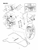

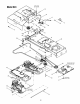

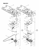


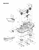

Model624
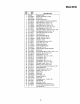
REF.
NO.
1
2
3
4
5
6
7
8
9
10
11
12
13
14
15
16
17
18
19
20
21
22
23
24
25
26
27
28
29
30
31
32
33
34
35
36
37
38
39
40
PART
NO.
683-0317
683-0318
683-0320
710-0227
710-0451
710-0514
710-0599
710-0604A
710-0642
710-0788
710-1260A
711-1509
711-1535
712-0298
712-0365
629-1083
712-3004A
712-3027
714-0507
716-0125
720-0278A
720-0322
725-1760
725-1773
725-1980
726-0209
726-0320
727-3113
732-0568
736-0169
736-0349
736-3004
783-1265
738-0255
741-0591
746-1121
748-0438
749-1236
749-1237
750-1298
DESCRIPTION
RH Handle Bracket Assembly
LH Handle Bracket Assembly
Bail Assembly
Self-tapping Screw, #8-18 x .5
Carriage Screw, 5/16-18 x .75
Hex Cap Screw, 3/8-16 x 1.0
Self-tapping Screw, 1/4-20 x .5
Self-tapping Screw, 16-18 x .625
Self-tapping Screw, 1/4-20 x .75
Self-tapping Screw, 1/4-20 x 1.0
Self-tapping Screw, 5/16-18 x .75
Control Shaft
Rod, .375 x 8.0
Jam Nut, 1/4-20
Center Lock Hex Nut, M8
Ground Jumper Wire Assembly
Flange Lock Nut, 5/16-18
Hex Flange Lock Nut, 1/4-20
Cotter Pin, 3/32 x .75
E-Ring, .375
Foam Grip
Dipped Cap, .187
Spring Switch
Short Spring Switch
Lever Spring Switch
Cable Tie
Insulator Nut Plate
Damper Cylinder
Extension Spring, .50 x 2.54
Lock Washer, 3/8
Flat Washer, .63 x 1.0 x .020
Flat Washer, .406 x .875 x .105
Clamp Cable Bracket
Shoulder Screw, .375 x. 181
Flange Bearing, .630 x .693
Control Cable, 77.5
Index Plate
Hand Rest Tube
Control Handle
Spacer, .280 x .437 x .250
NOTE: For painted parts, please refer to
the list of color codes below. Please add
the applicable color code, wherever
needed, to the part number to order a
replacement part. For instance, if a part
numbered 700-xxxx is painted Yard-Man
Green, the part number to order would be
700-xxxx-0665.
Yard-Man Green: 0665
Yard-Man Yellow: 0674
Powder Black: 0637
33