
Manual


MovingtheTractorManually
The Revolution TM lawn tractor has two transmissions,
both of which are equipped with a hydrostatic bypass
valve for occasions when it is necessary to move the
tractor manually.
Opening these valves forces the fluid in each
transmission to bypass its normal route, allowing the
rear tires to "freewheel." To open the hydrostatic
bypass valves, proceed as follows:
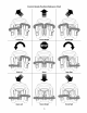
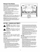
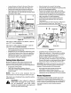
Locate the hydrostatic bypass rods in the rear of
the tractor. See Figure 12.
Pull both the hydrostatic bypass rods outward,
then up, to lock them in place.
NOTE: Neither transmission will engage when the
hydrostatic bypass rods are pulled out. Return the rods
to their normal position prior to operating the tractor.
IMPORTANT: Never attempt to move the tractor
manually without first opening both hydrostatic bypass
valves. Doing so will result in serious damage to the
tractor's transmissions.
Hydrostatic
Bypass Rods
Figure 12
SECTION7: MAKINGADJUSTMENTS
WARNING: Never attempt to make any
adjustments while the engine is running,
except where specified in the operator's
manual.
_, WARNING: Disconnect the spark plug
wire(s) and ground against the engine before
performing any adjustments, repairs or
maintenance.
Levelingthe Deck
NOTE: Check the tractor's tire pressure before
performing any deck leveling adjustments. Refer to
Tires later in this section for further information
regarding tire pressure.
FrontTo Rear
The front of the cutting deck is supported by a stabilizer
bar that can adjusted to level the deck from front to rear.
The front of the deck should be between 1!4-inch and
3/8-inch lower than the rear of the deck. Adjust if
necessary as follows:
With the tractor parked on a firm, level surface,
place the deck lift lever inthe top notch (highest
position) and rotate the blade nearest the discharge
chute so that it is parallel with the tractor.
Measure the distance from the front of the blade tip
to the ground and the rear of the blade tip to the
ground.
The first measurement taken should be between
1/4" and 3/8" less than the second measurement.
Determine the approximate distance necessary for
proper adjustment and proceed, if necessary, to the
next step.
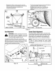
Loosen the two jam nuts on the rear side of the
deck stabilizer bracket. See Figure 13A.
Locate the two lock nuts on the opposite side of the
stabilizer bracket. See Figure 13A. Tighten the lock
nuts to raise the front of the deck; loosen the lock
nuts to lower the front of the deck.
Retighten the two jam nuts loosened earlier when
proper adjustment is achieved.
SidetoSide
If the cutting deck appears to be mowing unevenly, a
side to side adjustment can be performed. Adjust if
necessary as follows:
With the tractor parked on a firm, level surface,
place the deck lift lever in the top notch (highest
position) and rotate both blades so that they are
perpendicular with the tractor.
Measure the distance from the outside of the left
blade tip to the ground and the distance from the
outside of the right blade tip to the ground. Both
measurements taken should be equal. If they're
not, proceed to the next step.
Loosen, but do NOT remove, the hex cap screw on
the left deck hanger bracket. See Figure 13B.
18