
Manual
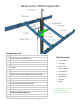
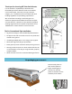
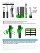
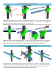
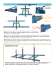
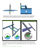
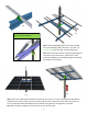
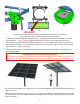

Table Of Contents

9
122
121B
NO GAP!!
121A
*Remove the gap by ghtening the square set bolts unl the front of the U-Bracket
is snug against pipe, then make one more full rotaon of the bolt.
121A: With the mount hanging free on the hoist, FIRST ghten the square-headed set bolts in the back
mounng plate.
Remove the gap by ghtening the set bolts unl the front of the U-Bracket is snug
against pipe, then make one more full rotaon of the bolt.
SECOND, ghten both long 3/4” bolts in back
mounng plate to 100 -lb.
Insert the last long 3/4" bolt over the top of the pole with the 3/4” at wash-
ers and 3/4” nut. Tighten to 20 lbs.
122: Remove the chain hoist and liing bracket and place the 2” square cap in place. Add spin preven-
on bolts as needed.
SINGLE POLE SPIN PREVENTION
For 12 panel mounts & larger, please see the Spin Prevenon Addendum at the end of this manual. This
provides a eld-drilled bolt-through opon for extra security of the U-bracket to the support pipe.
123 124
123: Place the nal module in the empty space. It may be advantageous to fully extend the Screw Adjuster to
make this easier.
125: Aach adjuster handle using the set screw. You may cut the handle to length depending on pole height
and site condions. We recommend occasional greasing of the threaded rod. Using an angle nder, adjust
array to proper lt.