SUPER M35S and M35T1 Mobile Rack USER'S GUIDE Rev. 1.
M35S and M35T1 Mobile Rack User's Guide The information in this User’s Manual has been carefully reviewed and is believed to be accurate. The vendor assumes no responsibility for any inaccuracies that may be contained in this document, makes no commitment to update or to keep current the information in this manual, or to notify any person or organization of the updates. Please Note: For the most up-to-date version of this manual, please see our web site at www.supermicro.com. Super Micro Computer, Inc.
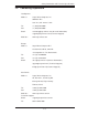
Safety Information and Technical Specifications Table of Contents Chapter 1 Introduction 1-1 Overview ......................................................................................................... 1-1 1-2 Product Features ........................................................................................... 1-1 Operating Systems Supported ........................................................................ 1-1 System Monitoring ........................................................
M35S and M35T1 Mobile Rack User's Guide Notes iv
Safety Information and Technical Specifications Chapter 1 Introduction 1-1 Overview This manual is written for system integrators, PC technicians and knowledgeable PC users who intend to integrate Supermicro's intelligent, highly expandable and costeffective mobile rack solutions into their systems. It provides the user with detailed information for the installation and use of the M35S/M35T1 mobile rack.
M35S and M35T1 Mobile Rack User's Guide System Monitoring • Fan failure LED • Overheat LED indicatior • Drive activity indicatior 1-3 An Important Note to the User The pictures or graphics shown in this User's Guide were based upon the latest PCB revision available at the time of the publishing of this manual. The M35S/ M35T1 mobile rack you've received may or may not look exactly the same as the graphics shown in this manual.
Safety Information and Technical Specifications 1-4 Contacting Supermicro Headquarters Address: Super Micro Computer, Inc. 980 Rock Ave. San Jose, CA 95131 U.S.A. Tel: +1 (408) 503-8000 Fax: +1 (408) 503-8008 Email: marketing@supermicro.com (General Information) support@supermicro.com (Technical Support) Web Site: www.supermicro.com Europe Address: Super Micro Computer B.V.
M35S and M35T1 Mobile Rack User's Guide 1-5 Returning Merchandise for Service A receipt or copy of your invoice marked with the date of purchase is required before any warranty service will be rendered. You can obtain service by calling your vendor for a Returned Merchandise Authorization (RMA) number. When returning to the manufacturer, the RMA number should be prominently displayed on the outside of the shipping carton, and mailed prepaid or hand-carried.
Safety Information and Technical Specifications Chapter 2 SATA-M35 and SCA-M942 Backplane Specifications To avoid personal injury and property damage, carefully follow all the safety steps listed below when accessing your system or handling the components. 2-1 ESD Safety Guidelines Electrostatic Discharge (ESD) can damage electronic components. To prevent damage to your system, it is important to handle it very carefully.
M35S and M35T1 Mobile Rack User's Guide 2-3 Introduction to SATA-M35 and SCA-M942 The M35S and M35T1 mobile racks include either a SATA or SCSI backplane. The M35S model comes equipped with an SCA-M942 SCSI backplane and the M35T1 comes equipped with a SATA-M35 Serial ATA (SATA) backplane. These backplanes are designed to utilize the most up-to-date technology available, providing your system with reliable, high-quality performance. This manual reflects models SATA-M35 Revision 1.
Safety Information and Technical Specifications Chapter 3 Backplane Connectors, Jumpers and LEDs 3-1 SATA-M35S Front Connectors and Jumpers 1 1 12 14 15 16 17 18 13 Figure 3-1: SATA-M35S Front Connectors Front Connectors 1. 4-pin Power Connectors: JP10 and JP13 5. SATA Port #2 (Channel 2): J6 6. SATA Port #3 (Channel 3): J7 2. ACT IN: JP26 7. SATA Port #4 (Channel 4): J8 3. Fan Connector: JP22 8. SATA Port #5 (Channel 5): J10 4.
M35S and M35T1 Mobile Rack User's Guide 3-2 Front Connectors and Pin Definitions 1. Mobile Rack Main Power Connectors Mobile rack Main Power 4-Pin Connector The 4-pin power connectors provide power to the mobile rack. See the table on the right for Pin# pin definitions. 1 +12V 2 and 3 Ground 4 +5V 2. Activity LED Connector Definition Activity LED Connector The activity LED connector, designated JP26, is used to indicate the activity status of each hard drive.
Safety Information and Technical Specifications 3-3 SATA-M35S Front Jumpers and Pin Definitions JP25 JP18 JP28 Figure 3-2: SATA-M35S Front Jumpers Jumper Settings Jumper Jumper Settings Note JP18 Open (jumper off): Buzzer enabled Closed (jumper on): Buzzer disabled Buzzer reset* JP28 1-2: Fan enabled 2-3: Fan disabled Fan jumper JP25 Open (jumper off): 45ºC 1-2: 50ºC 2-3: 55ºC Overheat temperature settings. Buzzer activated at the temperature indicated.
M35S and M35T1 Mobile Rack User's Guide Explanation of Jumpers To modify the operation of the mobile rack, 3 2 1 3 2 1 Connector Pins jumpers can be used to choose between optional settings. Jumpers create shorts between two pins to change the function Jumper of the connector. Pin 1 is identified with a square solder pad on the printed circuit board. Note: On two pin jumpers, "Closed" means the jumper is on and "Open" means the jumper is off the pins.
Safety Information and Technical Specifications 3-4 SCA-M942 Front Connectors and Jumpers 14 12 13 1 1 Figure 3-3: SCA-M942 Front Connectors Front Connectors 1. 4-pin Power Connectors: JP10 and JP13 3. 68-pin SCSI connector 4. Fan Connector: JP22 2.
M35S and M35T1 Mobile Rack User's Guide 3-5 SCA-M942 Front Connectors and Pin Definitions 1. Mobile Rack Main Power Connectors The 4-pin power connectors, designated JP10 and JP13, provide power to the mobile rack. Mobile rack Main Power 4-Pin Connector Pin# See the table on the right for pin definitions. Definition 1 +12V 2 and 3 4 Ground +5V 2. QLogic GEM 318 Chip The QLogic Gem 318 chip is an enclosure management chip that supports the SES-2 controller and SES-2 protocols. 3.
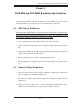
Safety Information and Technical Specifications 3-6 SCA-M942 Front Jumpers and Pin Definitions JP21 JP29 JP30 JP18 JP24 Figure 3-4: SCA-M942 Front Jumpers Jumper Settings Jumper Jumper Settings JP18 Open (jumper off) Disabled (Default) Close (jumper on) Enabled JP21 Open (jumper off) Disabled Close (jumper on) Enabled (Default) JP24 1-2: SCSI IDs 0,1,2,3,4 (Default) 2-3: SCSI IDs 9, 10, 11, 12, 13 JP29 1-2: ID6 (Default) 2-3: ID8 JP30 1-2: Enabled (Default) Alarm will sound if no fan is pr
Safety Information and Technical Specifications Chapter 4 Mobile Rack Installation Procedures 4-1 Tools Required The following tools are required to install the mobile rack into the chassis: • Phillips head screwdriver • Antistatic strap (recommended) 4-2 Important Safety Guidelines This product should be assembled and/or serviced by qualified and experienced technicians. To avoid personal injury and property damage, carefully follow the guidelines listed below. Safety Guidelines 1.
M35S and M35T1 Mobile Rack User's Guide 4-3 Installation Procedures Use the following installation procedures to set up the mobile rack. ! WARNING! SAS IDs are assigned automatically by the backplane. Do not set ID's manually on the drives. SAS termination is enabled by default on the SAS backplane. Removing Hard Drive Carriers from the Mobile Rack The hard drives of the M35S and M35T1 mobile racks are mounted in drive carriers to simplify their installation and removal from the chassis.
Safety Information and Technical Specifications Figure 4-2: Removing Hard Drives From the Mobile Rack 2. Use the drive handle to carefully pull the drive from the mobile rack.
M35S and M35T1 Mobile Rack User's Guide Installing Hard Drives into the Hard Drive Carriers Dummy Drive Hard Drive Carrier Figure 4-3: The Hard Drive Carrier and Dummy Drive ! Warning: Except for short periods of time while swapping hard drives, do not operate the server with the mobile rack hard drive bays empty. The hard drive carrier must have a hard drive or dummy drive installed.
Safety Information and Technical Specifications SATA or SCSI Hard Drive 14 14 Drive Tray Figure 4-4: Installing the Hard Drive into the Hard Drive Carrier 3. Install a new hard drive into the hard drive carrier with the printed circuit board side facing downward so that the mounting holes in the hard drive align with those in the hard drive carrier. 4. Secure the hard drive to the hard drive carrier with the six screws provided. 5. Return the hard drive carrier to the mobile rack.
M35S and M35T1 Mobile Rack User's Guide Connecting Cables to the Mobile Rack Before connecting cables the mobile rack, the exhaust fan must be removed. In some circumstances, the backplane may need to be removed. 1 1 Figure 4-5: Removing Mobile Rack Fan Removing the Exhaust Fan and Connecting Cables 1. Simultaneously press inward on the tabs on each side of the fan housing.
Safety Information and Technical Specifications 12 Figure 4-6: Removing Mobile Rack Fan 2. Pull the exhaust fan off the rear of the mobile rack. 13 Figure 4-7: Removing the Bracket Screw 3. Remove the bracket screw from the side of the mobile rack.
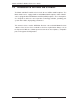
M35S and M35T1 Mobile Rack User's Guide 14 Figure 4-8: Removing Mobile Rack Bracket 4. Pull the bracket from the rear of the mobile rack. 5. Connect the SATA cables and power cables to the backplane of the mobile rack. 6. Replace the bracket, bracket screw, and fan on the mobile rack and reconnect power to the chassis.
Safety Information and Technical Specifications Backplane Screw Locations Figure 4-9: Removing the Mobile Rack Backplane (Optional) Additional Optional Installation Information If necessary, before reassembling the mobile rack, the backplane may be removed. To remove the mobile rack backplane, remove the six screws securing the backplane to the mobile rack. Carefully pull the backplane from the rear of the mobile rack.
M35S and M35T1 Mobile Rack User's Guide Disclaimer (cont.) The products sold by Supermicro are not intended for and will not be used in life support systems, medical equipment, nuclear facilities or systems, aircraft, aircraft devices, aircraft/emergency communication devices or other critical systems whose failure to perform be reasonably expected to result in significant injury or loss of life or catastrophic property damage.