
Specifications


Interrupts/diagnostics alarms
5.3 Diagnostics alarms
DI 32x24VDC HF digital input module (6ES7521-1BL00-0AB0)
40 Manual, 04/2015, A5E03485935-AE
5.3
Diagnostics alarms
Diagnostics alarms
A diagnostics alarm is generated and the ERROR-LED flashes for each diagnostics event on
the module. The diagnostics alarms can, for example, be read out in the diagnostics buffer of
the CPU. You can evaluate the error codes with the user program.
If the module is operated distributed with PROFIBUS DP in an ET 200MP system, you have
the option to read out diagnostics data with the instruction RDREC or RD_REC using data
record 0 and 1. The structure of the data records is available on the Internet in the "Manual
for interface module IM 155-5 DP ST (6ES7155-5BA00-0AB0)".
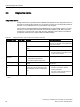
Table 5- 5 Diagnostics alarms, their meaning and corrective measures
Diagnostics alarm
Error code
Meaning
Corrective measures
Wire break* 6
H
Impedance of encoder circuit too high Use a different encoder type or modify
the wiring, for example, using cables with
larger cross-section
Wire break between the module and
sensor
Connect the cable
Channel not connected (open)
• Disable diagnostics
• Connect a resistor of 25 kΩ to 45 kΩ
to the encoder contacts
Parameter assign-
ment error
10
H
• The module cannot evaluate
parameters for the channel
• Incorrect parameter assignment
Correct the parameter assignment
Load voltage missing 11
H
Supply voltage L+ of the module is
missing
Connect supply voltage L+ to mod-
ule/channel
Hardware interrupt
lost
16
H
The module cannot trigger an interrupt
because the previous interrupt was not
acknowledged; possibly a configuration
error
• Change interrupt processing in the
CPU and, if necessary, edit the
module parameters.
• The error persists until the module is
assigned new parameters
* If the supply voltage fails in case of a pending wire break diagnostics, the value status momentarily indicates an
incorrect
value.