
Specifications


Parameters/address space
4.1 Parameter
DI 32x24VDC HF digital input module (6ES7521-1BL00-0AB0)
16 Manual, 04/2015, A5E03485935-AE
4.1.1
Parameters DI mode
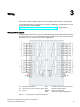
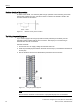
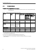
Parameters of the DI 32x24VDC HF in the DI mode
In the following table, you will find the parameters in the "DI mode". These parameters apply
to channels 0 to 31.
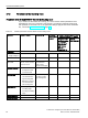
Table 4- 1 Settable parameters and their defaults in the DI mode
Parameter
Range of
values
Default setting
Parameter reas-
signment in RUN
Range of effectiveness with
configuration software, e.g. STEP 7
Integrated in the
hardware catalog
as of STEP 7,
V13 SP1 or GSD
file PROFINET IO
GSD file
PROFIBUS DP
Diagnostics
• No
supply voltage L+
Yes/No No Yes Channel* Channel group**
• Wire break
Yes/No No Yes Channel Channel group**
Input delay
0.05 ms,
0.1 ms, 0.4 ms,
1.6 ms, 3.2 ms,
12.8 ms, 20 ms
3.2 ms;
for isochronous
mode 0.05 ms
(cannot be
changed)
Yes Channel Channel group**
Hardware interrupt***
• Rising edge
Yes/No No Yes Channel Channel
• Falling edge
Yes/No No Yes Channel Channel
• Rising and falling edge
Yes/No No Yes Channel Channel
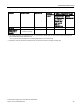
* If you enable diagnostics for multiple channels, you will receive an alarm surge on failure of
the supply voltage because
each enabled channel will detect this fault.
You can prevent this message burst by enabling diagnostics for one channel only.
** The scope can be assigned for each channel during parameter assignment in RUN.
*** For the configur
ation as a 4 x 8-channel module, a maximum of 16 hardware interrupts can be configured
(channels 0 to 15).