
Specifications


DI 32x24VDC HF digital input module (6ES7521-1BL00-0AB0)
Manual, 04/2015, A5E03485935-AE
13
Wiring
3
This section contains the block diagram of the module and outlines various wiring options.
You will find information on wiring the front connector, establishing a cable shield, etc in the
system manual S7-1500/ET 200MP
(http://support.automation.siemens.com/WW/view/en/59191792) in section Wiring.
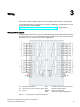
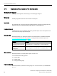
Wiring and block diagram
The figure below shows how to wire the module and assign channel addresses (input byte a
up to input byte d). You can set parameters so that channels 0 and 1 are used for counting.
Channels 2 to 31 can continue to be used as digital inputs.
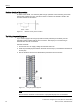
①
Backplane bus interface
CHx
Channel or LED channel status (green)
xL+
Power supply 24 V DC for relay contacts
RUN
LED status display (green)
xM
Ground
ERROR
LED error display (red)
PWR
LED supply voltage POWER (green)
Figure 3-1 Block diagram and terminal assignment