
Specifications


Wiring
DI 16x24VDC HF Digital Input Module (6ES7521-1BH00-0AB0)
12 Manual, 07/2014, A5E03485952-AD
Wiring and block diagrams
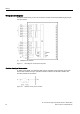
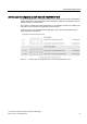
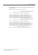
The figure below shows you how to connect the module and channel addressing (input byte
a to input byte b).
①
Backplane bus interface
Figure 3-1 Block diagram and terminal assignment
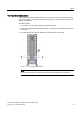
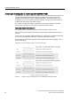
Resistor circuitry of the encoders
To detect a wire break, it is necessary that enough quiescent current is flowing even when
the encoder contacts are open. Connect a resistor of 25 kΩ to 45 kΩ with 0.25 W to the
encoder contacts for this reason.
Figure 3-2 Resistor circuitry of the encoders