SIMATIC S7-1500 Digital input module DI 16x24VDC HF (6ES7521-1BH00-0AB0) Manual Edition 07/2014 Answers for industry.
DI 16x24VDC HF Digital Input Module ___________________ Preface (6ES7521-1BH00-0AB0) 1 ___________________ Documentation guide SIMATIC S7-1500/ET 200MP DI 16x24VDC HF Digital Input Module (6ES7521-1BH00-0AB0) Manual 2 ___________________ Product overview 3 ___________________ Wiring 4 ___________________ Parameters/address space 5 ___________________ Interrupts/diagnostics alarms 6 ___________________ Technical specifications A ___________________ Dimensional drawing B ___________________ Parameter dat
Legal information Warning notice system This manual contains notices you have to observe in order to ensure your personal safety, as well as to prevent damage to property. The notices referring to your personal safety are highlighted in the manual by a safety alert symbol, notices referring only to property damage have no safety alert symbol. These notices shown below are graded according to the degree of danger.
Preface Purpose of the documentation This manual supplements the system manuals: ● S7-1500 Automation System ● ET 200MP Distributed I/O System Functions that relate in general to the systems are described in these system manuals. The information provided in this manual and in the system/function manuals supports you in commissioning the systems.
Preface Security information Siemens provides products and solutions with industrial security functions that support the secure operation of plants, solutions, machines, equipment and/or networks. They are important components in a holistic industrial security concept. With this in mind, Siemens’ products and solutions undergo continuous development. Siemens recommends strongly that you regularly check for product updates.
Table of contents Preface ................................................................................................................................................... 3 1 Documentation guide .............................................................................................................................. 6 2 Product overview .................................................................................................................................... 8 2.1 Properties ............
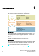
1 Documentation guide The documentation for the SIMATIC S7-1500 automation system and the SIMATIC ET 200MP distributed I/O system is arranged into three areas. This arrangement enables you to access the specific content you require. Basic information System Manual and Getting Started describe in detail the configuration, installation, wiring and commissioning of the SIMATIC S7-1500 and ET 200MP systems. The STEP 7 online help supports you in the configuration and programming.
Documentation guide Manual Collection S7-1500 / ET 200MP The Manual Collection contains the complete documentation on the SIMATIC S7-1500 automation system and the ET 200MP distributed I/O system gathered together in one file. You can find the Manual Collection on the Internet (http://support.automation.siemens.com/WW/view/en/86140384). My Documentation Manager The My Documentation Manager is used to combine entire manuals or only parts of these to your own manual.
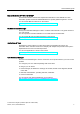
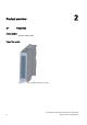
2 Product overview 2.
Product overview 2.1 Properties Properties The module has the following technical properties: ● 16 digital inputs; electrically isolated in groups of 16 ● Rated input voltage 24 V DC ● Configurable input delay: 0.
Product overview 2.1 Properties Other components The following component must be ordered separately: Front connectors, including potential jumpers and cable ties You can find more information on accessories in the S7-1500 Automation System (http://support.automation.siemens.com/WW/view/en/59191792) system manual and the ET 200MP Distributed I/O System (http://support.automation.siemens.com/WW/view/en/59193214) system manual.
3 Wiring This section contains the block diagram of the module and outlines various connection options. For more information on front connector wiring and creating cable shields, for example, refer to the "Wiring" section in the S7-1500 Automation System (http://support.automation.siemens.com/WW/view/en/59191792) and ET 200MP distributed I/O system (http://support.automation.siemens.com/WW/view/en/59193214) system manuals.
Wiring Wiring and block diagrams The figure below shows you how to connect the module and channel addressing (input byte a to input byte b). ① Backplane bus interface Figure 3-1 Block diagram and terminal assignment Resistor circuitry of the encoders To detect a wire break, it is necessary that enough quiescent current is flowing even when the encoder contacts are open. Connect a resistor of 25 kΩ to 45 kΩ with 0.25 W to the encoder contacts for this reason.
Wiring Tip: Using the potential jumpers Use the potential jumpers supplied with the front connector if you want to distribute the 24V DC supply voltage to a neighboring module. This helps you to avoid having to terminate two wires to one terminal. Proceed as follows: 1. Connect the 24 V DC supply voltage to terminals 19 and 20. 2. Insert the potential jumpers between terminals 19 and 39 (L+) and between terminals 20 and 40 (M). 3.
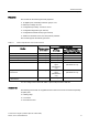
4 Parameters/address space 4.1 Parameters DI 16x24VDC HF parameters When you assign the module parameters in STEP 7, you use various parameters to specify the module properties. The following table lists the configurable parameters. The effective range of the configurable parameters depends on the type of configuration.
Parameters/address space 4.2 Address space Parameters Range of values Default Parameter assignment in RUN Scope with configuration software, e.g.
Parameters/address space 4.2 Address space Value status (Quality Information, QI) The value status is always activated for the following module names: ● DI 16x24VDC HF QI, ● DI 16x24VDC HF QI S ● DI 16x24VDC HF MSI An additional bit is assigned to each channel for the value status. The value status bit indicates if the read in digital value is valid. (0 = value is incorrect).
Parameters/address space 4.2 Address space Address space for configuration as 2 x 8-channel DI 16x24VDC HF QI S For the configuration as a 2 x 8-channel module, the channels of the module are divided into multiple submodules. The submodules can be assigned to different IO controllers when the module is used in a shared device. The number of usable submodules is dependent on the interface module used. Observe the information in the manual for the particular interface module.
Parameters/address space 4.2 Address space Address space for configuration as 1 x 16-channel DI 16x24VDC HF MSI The channels 0 to 15 of the module are copied in up to four submodules with configuration 1 x 16-channel module (Module-internal shared input, MSI). Channels 0 to 15 are then available with identical input values in different submodules. These submodules can be assigned to up to four IO controllers when the module is used in a shared device.
Parameters/address space 4.2 Address space The following figure shows the assignment of the address space with submodules 3 and 4 and the value status.
5 Interrupts/diagnostics alarms 5.1 Status and error displays LED displays The following figure shows the LED displays (status and error displays) of DI 16x24VDC HF.
Interrupts/diagnostics alarms 5.1 Status and error displays Meaning of the LED displays The following tables explain the meaning of the status and error displays. Remedial measures for diagnostic reports can be found in chapter Diagnostics alarms (Page 24). RUN and ERROR LED Table 5- 1 Status and error displays RUN and ERROR LED Meaning RUN ERROR Off Off Voltage missing or too low at backplane bus Flashes Off The module starts and flashes until the valid parameter assignment is set.
Interrupts/diagnostics alarms 5.1 Status and error displays CHx LED Table 5- 3 CHx status display LED CHx Meaning Remedy 0 = Status of the input signal --- 1 = Status of the input signal --- Diagnostics: Wire break Check the wiring. When using simple switches, deactivate diagnostics or connect a resistor (25 kΩ … 45 kΩ) to the encoder contacts. Supply voltage L+ too low or missing Check supply voltage L+.
Interrupts/diagnostics alarms 5.2 Interrupts 5.2 Interrupts Digital input module DI 16x24VDC HF supports diagnostic and hardware interrupts.
Interrupts/diagnostics alarms 5.3 Diagnostics alarms Structure of the additional interrupt information Table 5- 4 Structure of USI = W#16#0001 Data block name Contents Comment Bytes USI W#16#0001 Additional interrupt info for hardware interrupts of the I/O module 2 Number of the event-triggering channel (channel 0 to channel 15 of the module) 1 B#16#01 Positive edge 1 B#16#02 Negative edge (User Structure Identifier) The channel that triggered the hardware interrupt follows.
Interrupts/diagnostics alarms 5.
6 Technical specifications Technical specifications of the DI 16x24VDC HF 6ES7521-1BH00-0AB0 Product type designation DI 16x24VDC HF General information Hardware version E01 Firmware version V2.0.0 Product function I&M data Yes; IM0 to IM3 Engineering with STEP 7 TIA Portal can be configured/integrated as of version V12.0 / V12.0 STEP 7 can be configured/integrated as of version as of V5.
Technical specifications 6ES7521-1BH00-0AB0 Input current for signal "1", typ. 2.5 mA Input delay (for rated value of input voltage) For standard inputs • Configurable Yes; 0.05 / 0.1 / 0.4 / 1.6 / 3.2 / 12.8 / 20 ms • with "0" to "1", min. 0.05 ms • with "0" to "1", max. 20 ms • with "1" to "0", min. 0.05 ms • with "1" to "0", max. 20 ms For interrupt inputs • Configurable Yes Cable length Cable length shielded, max. 1000 m Cable length unshielded, max.
Technical specifications 6ES7521-1BH00-0AB0 Electrical isolation Electrical isolation of channels Between the channels No Between the channels, in groups of 16 Between the channels and the backplane bus Yes Between the channels and the supply voltage of the electronics No Permitted potential difference Between different circuits 75 V DC / 60 V AC (basic isolation) Isolation Isolation tested with 707 V DC (type test) Distributed mode Prioritized startup Yes Dimensions Width 35 mm Height 147
Dimensional drawing A The dimensional drawing of the module on the mounting rail, as well as a dimensional drawing with open front cover, are provided in the appendix. Always observe the specified dimensions for installation in cabinets, control rooms, etc.
Dimensional drawing Figure A-2 Dimensional drawing of the DI 16x24VDC HF module, side view with open front cover DI 16x24VDC HF Digital Input Module (6ES7521-1BH00-0AB0) 30 Manual, 07/2014, A5E03485952-AD
Parameter data records B.1 B Parameter assignment and structure of the parameter data records The data records of the module have an identical structure, regardless of whether you configure the module with PROFIBUS DP or PROFINET IO. Dependencies for configuration with GSD file When a GSD file is used to configure a module, dependencies can arise when "assigning the parameters". There are no dependencies for this module. You can assign the individual parameters in any combination.
Parameter data records B.1 Parameter assignment and structure of the parameter data records Assignment of data record and channel For the configuration as a 1 x 16-channel module, the parameters are located in data records 0 to 15 and are assigned as follows: ● Data record 0 for channel 0 ● Data record 1 for channel 1 ● … ● Data record 14 for channel 14 ● Data record 15 for channel 15 For the configuration as a 2 x 8-channel module, the module has 2 submodules with eight channels each.
Parameter data records B.1 Parameter assignment and structure of the parameter data records Data record structure The example in the following figure shows the structure of data record 0 for channel 0. The structure of channels 1 to 15 is identical. The values in byte 0 and byte 1 are fixed and may not be changed. Enable a parameter by setting the corresponding bit to "1".
C Open Source Software For resellers: In order to avoid infringements of the license conditions by the reseller or the buyer, these instructions and license conditions have to be forwarded to the buyers.
Open Source Software DI 16x24VDC HF Digital Input Module (6ES7521-1BH00-0AB0) Manual, 07/2014, A5E03485952-AD 35
Open Source Software DI 16x24VDC HF Digital Input Module (6ES7521-1BH00-0AB0) 36 Manual, 07/2014, A5E03485952-AD
Open Source Software DI 16x24VDC HF Digital Input Module (6ES7521-1BH00-0AB0) Manual, 07/2014, A5E03485952-AD 37
Open Source Software DI 16x24VDC HF Digital Input Module (6ES7521-1BH00-0AB0) 38 Manual, 07/2014, A5E03485952-AD
Open Source Software DI 16x24VDC HF Digital Input Module (6ES7521-1BH00-0AB0) Manual, 07/2014, A5E03485952-AD 39
Open Source Software DI 16x24VDC HF Digital Input Module (6ES7521-1BH00-0AB0) 40 Manual, 07/2014, A5E03485952-AD
Open Source Software DI 16x24VDC HF Digital Input Module (6ES7521-1BH00-0AB0) Manual, 07/2014, A5E03485952-AD 41
Open Source Software DI 16x24VDC HF Digital Input Module (6ES7521-1BH00-0AB0) 42 Manual, 07/2014, A5E03485952-AD
Open Source Software DI 16x24VDC HF Digital Input Module (6ES7521-1BH00-0AB0) Manual, 07/2014, A5E03485952-AD 43
Open Source Software DI 16x24VDC HF Digital Input Module (6ES7521-1BH00-0AB0) 44 Manual, 07/2014, A5E03485952-AD
Open Source Software DI 16x24VDC HF Digital Input Module (6ES7521-1BH00-0AB0) Manual, 07/2014, A5E03485952-AD 45