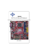
PM8PM MS-7222 (v1.
FCC-B Radio Frequency Interference Statement This equipment has been tested and found to comply with the limits for a class B digital device, pursuant to part 15 of the FCC rules. These limits are designed to provide reasonable protection against harmful interference in a residential installation. This equipment generates, uses and can radiate radio frequency energy and, if not installed and used in accordance with the instruction manual, may cause harmful interference to radio communications.
Copyright Notice The material in this document is the intellectual property of MICRO-STAR INTERNATIONAL. We take every care in the preparation of this document, but no guarantee is given as to the correctness of its contents. Our products are under continual improvement and we reserve the right to make changes without notice. Trademarks All trademarks are the properties of their respective owners. AMD, Athlon™, Athlon™ XP, Thoroughbred™, and Duron™ are registered trademarks of AMD Corporation.
Technical Support If a problem arises with your system and no solution can be obtained from the user’s manual, please contact your place of purchase or local distributor. Alternatively, please try the following help resources for further guidance. † Visit the MSI homepage & FAQ site for technical guide, BIOS updates, driver updates, and other information: http://www.msi.com.tw & http://www.msi. com.tw/program/service/faq/faq/esc_faq_list.php † Contact our technical staff at: support@msi.com.
WEEE Statement v
vi
vii
CONTENTS Chapter 1. Getting Started ............................................................................... 1-1 Mainboard Specifications ............................................................................... 1-2 Mainboard Layout ........................................................................................... 1-4 Packing Contents ............................................................................................ 1-5 MSI Special Feature ....................................
BIOS Flash Jumper: JWP1 ..................................................................... 2-20 Slots .............................................................................................................. 2-21 PCI Interrupt Request Routing ............................................................... 2-21 AGP (Accelerated Graphics Port) Slot ................................................. 2-21 PCI (Peripheral Component Interconnect) Slots .................................... 2-21 Chapter 3.
Getting Started Chapter 1. Getting Started Getting Started Thank you for choosing the PM8PM(MS-7222 v1.X) Series ATX mainboard. The PM8PM mainboard is based on VIA® P4M800 Pro and VIA® VT8237R Plus chipset for optimal system efficiency. Designed to fit the advanced Intel ® Pentium 4 Prescott LGA775 processor, the PM8PM mainboard delivers a high performance and professional desktop platform solution.
MS-7222 Micro-ATX Mainboard Mainboard Specifications CPU* † Supports Intel® Pentium ® 4/ Prescott (LGA 775) processor. † FSB @ 1066/800/533MHz. † Supports Intel P4 Prescott CPU up to 3.8GHz, and Intel P4 Prescott Celeron CPU. † Supports Dual Core CPU (2.8G only) † Supports Cedarmill CPU Chipset † VIA® P4M800Pro chipset - Supports P4 processors FSB (1066/800MHz). - Supports DDR SDRAM memory (DDRII 533/400). - Supports AGP 8x. - Supports 8X V-Link.
Getting Started Audio † AC97 link controller integrated in VT8237R plus. † Realtek ALC655 6-channel software audio codec. - Compliance with AC’97 v2.2 spec. LAN(optional) † Realtek® 8100C / 8110SB (optional). - Supports 10Mb/s, 100Mb/s and 1000Mb/s(1000Mb/s for 8110SB only). - Compliance with PCI 2.2. - Supports ACPI Power Management. 1394 (optional) † Support two IEEE 1394 on board pinheaders transfer rate is up to 400Mbps. † Controlled by VIA6307 chipset.
MS-7222 Micro-ATX Mainboard SYS_FAN1 DIMM2 Top : mouse Bottom: keyboard DIMM1 Mainboard Layout CONN1 CPU_FAN1 Top : Parallel Port Bottom: COM Port VGA Port Bottom: USB ports VIA P4M800PRO JPW2 IDE 2 T:MIC-In M:Line- In B:SS Out IDE 1 Top: LAN jack Bottom: USB ports COM2 Winbond W83627EHF AGP Slot BATT + PCI Slot 2 PLUS JBAT2 RTL8100C SATA2 VIA VT8237R SATA1 PCI Slot 1 VIA VT6307 (Optional) PCI Slot 3 BIOS JWP1 AC97 (Optional) (Optional) JAUDIO01 CD_IN1 FDD 1 1394_J2 1394_J3
Getting Started Packing Contents MSI motherboard MSI Driver/Utility CD SATA Cable Power Cable COM2 Bracket (Optional) Round Cable for IDE Devices (Optional) Back IO Shield Round Cable for Floppy Disk (Optional) User’s Guide * The pictures are for reference only. Your packing contents may vary depending on the model you purchased.
MS-7222 Micro-ATX Mainboard MSI Special Feature The Core Center is a new utility you can find in the CD-ROM disk. The utility is just like your PC doctor that can detect, view and adjust the PC hardware and system status during real time operation. In the left side it shows the current system status, including the Vcore, 3.3V, +5V and 12V. In the right side it shows the current PC hardware status such as the CPU & system temperatures and all fans speeds.
Getting Started Left-wing: Current system status In the left sub-menu, you can configure the settings of FSB, Vcore, Memory Voltage and AGP Voltage by clicking the radio button next to each item and make it available (the radio button will be lighted as yellow when selected), use the “+” and “-” buttons to adjust, then click “OK” to apply the changes. Then you can click “Save” to save the values you just configured. Also you may click “Auto” to start testing the maximum CPU overclocking value.
Hardware Setup Chapter 2. Hardware Setup Hardware Setup This chapter tells you how to install the CPU, memory modules, and expansion cards, as well as how to setup the jumpers on the mainboard. Also, it provides the instructions on connecting the peripheral devices, such as the mouse, keyboard, etc. While doing the installation, be careful in holding the components and follow the installation procedures.
MS-7222 Micro-ATX Mainboard Quick Components Guide CPU_FAN1, p.2-13 JPW2, p.2-8 DDR DIMMs, p.2-7 SYS_FAN1, p.2-13 CONN1, p.2-8 Back Panel I/O, p.2-9 IDE1, p.2-14 COM2, p.2-14 AGP, p.2-21 + SATA1,2, p.2-15 JBAT2, p.2-20 PCI Slots 1~3, p.2-21 JPW1, p.2-20 JFP1, p.2-16 JAUDIO1, p.2-17 CD_IN1, p.2-16 2-2 FDD1, p.2-13 1 3 9 4 _ J 2 ,3 , p.2-19 JUSB1,2 p.
Hardware Setup Central Processing Unit: CPU The mainboard supports Intel® Pentium 4 Prescott processor. The mainboard uses a CPU socket called LGA775. When you are installing the CPU, make sure to install the cooler to prevent overheating. If you do not have the CPU cooler, contact your dealer to purchase and install them before turning on the computer. For the latest information about CPU, please visit http://www.msi.com.tw/ program/products/mainboard/mbd/pro_mbd_cpu_support.php. MSI Reminds You...
MS-7222 Micro-ATX Mainboard CPU & Cooler Installation When you are installing the CPU, make sure the CPU has a cooler attached on the top to prevent overheating. If you do not have the cooler, contact your dealer to purchase and install them before turning on the computer. Meanwhile, do not forget to apply some silicon heat transfer compound on CPU before installing the heat sink/cooler fan for better heat dispersion. Follow the steps below to install the CPU & cooler correctly.
Hardware Setup 5. Lift the load lever up and open the load plate. 6. After confirming the CPU direction for correct mating, put down the CPU in the socket housing frame. Be sure to grasp on the edge of the CPU base. Note that the alignment keys are matched. alignment key 7. Visually inspect if the CPU is seated well into the socket. If not, take out the CPU with pure vertical motion and reinstall. 8. Cover the load plate onto the package. MSI Reminds You... 1.
MS-7222 Micro-ATX Mainboard 9. Press down the load lever lightly onto the load plate, and then secure the lever with the hook under retention tab. 10. Align the holes on the mainboard with the heatsink. Push down the cooler until its four clips get wedged into the holes of the mainboard. 11. Press the four hooks down to fasten the cooler. Then rotate the locking switch (refer to the correct direction marked on it) to lock the hooks. 12.
Hardware Setup Memory The mainboard provides 2 slots for 240-pin DDR2 DIMM, which supports the memory size up to 2GB. Since DDR2 modules are not interchangeable with DDR1 and the DDR2 standard is not backward compatible, you should always install DDR2 memory module in the DDR2 slot. Otherwise, you are not able to boot up your system and your mainboard might be damaged. Introduction to DDR2 SDRAM DDR2 is a new technology of memory module, and its speed is the top limit of current DDR1 technology.
MS-7222 Micro-ATX Mainboard Power Supply The mainboard supports ATX power supply for the power system. Before inserting the power supply connector, always make sure that all components are installed properly to ensure that no damage will be caused. ATX 24-Pin Power Connector: CONN1 The mainboard supports ATX power supply for the power system. Before inserting the power supply connector, always make sure that all components are installed properly to ensure that no damage will be caused.
Hardware Setup Back Panel The back panel provides the following connectors: LAN (optional) Parallel M ouse COM Port Keyboard USB Ports VGA Port L-In L-Out Mic Mouse/Keyboard Connector The mainboard provides a standard PS/2® mouse/keyboard mini DIN connector for attaching a PS/2® mouse/keyboard. You can plug a PS/2® mouse/keyboard directly into this connector.
MS-7222 Micro-ATX Mainboard Serial Port Connector The mainboard offers one 9-pin male DIN connector as the serial port. The port is a 16550A high speed communication port that sends/receives 16 bytes FIFOs. You can attach a serial mouse or other serial devices directly to the connector.
Hardware Setup USB Connectors The mainboard provides an OHCI (Open Host Controller Interface) Universal Serial Bus root for attaching USB devices such as keyboard, mouse or other USBcompatible devices. You can plug the USB device directly into the connector.
MS-7222 Micro-ATX Mainboard Parallel Port Connector: LPT1 The mainboard provides a 25-pin female centronic connector as LPT. A parallel port is a standard printer port that supports Enhanced Parallel Port (EPP) and Extended Capabilities Parallel Port (ECP) mode.
Hardware Setup Connectors The mainboard provides connectors to connect to FDD, IDE HDD, case, LAN, and USB Ports. Floppy Disk Drive Connector: FDD1 The mainboard provides a standard floppy disk drive connector that supports 360K, 720K, 1.2M, 1.44M and 2.88M floppy disk types. FDD1 (Black) Fan Power Connectors: CPU_FAN1/ SYS_FAN1 The CPU_FAN1(processor fan) and SYS_FAN1 (system fan) support system cooling fan with +12V. It supports four/three-pin head connector.
MS-7222 Micro-ATX Mainboard Hard Disk Connectors: IDE1, IDE2 The mainboard has one 32-bit Ultra DMA 66/100 IDE controller integrated in ICH6, which supports PIO & Bus Master operation modes and it can connect up to two Ultra ATA drives. IDE2 IDE1 IDE1 (Primary IDE Connector) IDE1 can connect a Master and a Slave drive. You must configure second hard drive to Slave mode by setting the jumper accordingly. IDE2 (Secondary IDE Connector) IDE2 can also connect a Master and a Slave drive. MSI Reminds You...
Hardware Setup Serial ATA: SATA1,SATA2 The SouthBridge of this mainboard supports two serial ATA connectors SATA1, SATA2. SATA1, SATA2 are dual high-speed Serial ATA interface ports. Each supports 1st generation serial ATA data rates of 150 MB/s. Both connectors are fully compliant with Serial ATA 1.0 specifications. Each Serial ATA connector can connect to 1 hard disk device.
MS-7222 Micro-ATX Mainboard Front Panel Connectors: JFP1 The mainboard provides one front panel connector for electrical connection to the front panel switches and LEDs. JFP1 is compliant with Intel ® Front Panel I/O Connectivity Design Guide.
Hardware Setup Front Panel Audio Connector: JAUDIO1 The JAUD1 front panel audio connector allows you to connect to the front panel audio and is compliant with Intel® Front Panel I/O Connectivity Design Guide.
MS-7222 Micro-ATX Mainboard Front USB Connectors: JUSB1 & JUSB2 The mainboard provides two standard USB 2.0 pin headers JUSB1 & JUSB2 . USB 2.0 technology increases data transfer rate up to a maximum throughput of 480Mbps, which is 40 times faster than USB 1.1, and is ideal for connecting highspeed USB interface peripherals such as USB HDD, digital cameras, MP3 players, printers, modems and the like.
Hardware Setup IEEE 1394 Connectors (optional): 1394_J2/ 1394_J3 The mainboard provides two 1394 pin headers that allows you to connect IEEE 1394 ports via an external IEEE1394 bracket (optional).
MS-7222 Micro-ATX Mainboard Jumpers The motherboard provides the following jumpers for you to set the computer’s function. This section will explain how to change your motherboard’s function through the use of jumpers. Clear CMOS Jumper: JBAT2 There is a CMOS RAM on board that has a power supply from external battery to keep the system configuration data. With the CMOS RAM, the system can automatically boot OS every time it is turned on.
Hardware Setup Slots The mainboard provides one AGP slot and three 32-bit PCI bus slots. AGP (Accelerated Graphics Port) Slot The AGP slot allows you to insert the AGP graphics card. AGP is an interface specification designed for the throughput demands of 3D graphics. It introduces a 66MHz, 32-bit channel for the graphics controller to directly access main memory. The slot supports 8x/4x AGP card.
BIOS Setup Chapter 3. BIOS Setup BIOS Setup This chapter provides information on the BIOS Setup program and allows you to configure the system for optimum use. You may need to run the Setup program when: ² An error message appears on the screen during the system boot up, and requests you to run SETUP. ² You want to change the default settings for customized features. MSI Reminds You... 1. The items under each BIOS category described in this chapter are under continuous update for better system performance.
MS-7222 Micro-ATX Mainboard Entering Setup Power on the computer and the system will start POST (Power On Self Test) process. When the message below appears on the screen, press key to enter Setup. Press F1 to continue, DEL to enter SETUP If the message disappears before you respond and you still wish to enter Setup, restart the system by turning it OFF and On or pressing the RESET button. You may also restart the system by simultaneously pressing , , and keys.
BIOS Setup The Main Menu Once you enter BIOS SETUP UTILITY, the Main Menu will appear on the screen. Use arrow keys to move among the items and press to enter the sub-menu. Standard CMOS Features Use this menu for basic system configurations, such as time, date etc. Advanced BIOS Features Use this menu to setup the items of AMI® special enhanced features. Advanced Chipset Features Use this menu to change the values in the chipset registers and optimize your system’s performance.
MS-7222 Micro-ATX Mainboard Load Optimized Defaults Use this menu to load the default values set by the mainboard manufacturer specifically for optimal performance of the mainboard. BIOS Setting Password Use this menu to set the password for BIOS. Save & Exit Setup Save changes to CMOS and exit setup. Exit Without Saving Abandon all changes and exit setup.
BIOS Setup Standard CMOS Features The items in Standard CMOS Features Menu includes some basic setup items. Use the arrow keys to highlight the item and then use the <+> or <-> keys to select the value you want in each item. Date (mm:dd:yy) This allows you to set the system to the date that you want (usually the current date). The format is . day Day of the week, from Sun to Sat, determined by BIOS. Read only. month The month from Jan. through Dec.
MS-7222 Micro-ATX Mainboard DMA Mode This item allows you to enable or disable the DMA (Direct Memory Access) mode. Setting options: [Auto], [Disabled], [UDMA0], [UDMA1], [UDMA2], [UDMA3], [UDMA4], [UDMA5]. Floppy A This item allows you to set the type of the floppy drives installed. Available options: [Disabled], [360 KB, 51/4], [1.2 MB, 51/4], [720 KB, 3 1/2], [1.44 MB, 3 1/2], [2.88MB, 3 1/2]. Halt On The setting determines whether the system will stop if an error is detected at boot.
BIOS Setup Advanced BIOS Features Quick Booting Setting the item to [Enabled] allows the system to boot within 5 seconds since it will skip some check items. Setting options: [Enabled], [Disabled]. CPU Feature Press to for the sub-menu of each item: Limit CPUID MaxVal: The item allows you to enable/ disable the CPU ID maximum value. [Enabled] Set to [Enabled] only when you have Prescott CPU and NT4.0 operating system. [Disabled] Set to [Disabled] if you have operating system other than NT4.0.
MS-7222 Micro-ATX Mainboard MSI Reminds You... Enabling the functionality of Hyper-Threading Technology for your computer system requires ALL of the following platform Components: * CPU: An Intel® Pentium® 4 Processor with HT Technology; * Chipset: An Intel® Chipset that supports HT Technology; * BIOS: A BIOS that supports HT Technology and has it enabled; * OS: An operating system that supports HT Technology. For more information on Hyper-threading Technology, go to: www.intel.
BIOS Setup Advanced Chipset Features MSI Reminds You... Change these settings only if you are familiar with the chipset. DRAM Clock/Drive Control Press and the following sub-menu appears. DRAM Clock Use this field to configure the clock frequency of the installed DRAM. Settings: By SPD, DDR 266 [3:2], DDR 333 [6:5], DDR 400 [1:1], DDR 433, DDR 450, DDR 466, DDR 500, DDR 533. MSI Reminds You... The value plus a ratio (CPU: DDR) with parentheses means the nonsynchronous overclocking.
MS-7222 Micro-ATX Mainboard DRAM Timing Selects whether DRAM timing is controlled by the SPD (Serial Presence Detect) EEPROM on the DRAM module. Setting to [Auto By SPD] enables the following fields automatically to be determined by BIOS based on the configurations on the SPD. Selecting [Manual] allows users to configure these fields manually. SDRAM CAS Latency [DDR/DDR2] This controls the timing delay (in clock cycles) before SDRAM starts a read command after receiving it. Settings: [1.5/ 2], [2/ 3], [2.
BIOS Setup Write to Read CMD (Twtr) This item controls the internal Write to Read Command Delay. Setting options: [1T/ 2T], [2T/3T]. Write Recovery Time (Twr) This function specifies the amount of delay (in clock cycles) that must elapse after the completion of a valid write operation, before an active bank can be precharged. This delay is required to guarantee that data in the write buffers can be written to the memory cells before precharge occurs. Setting options: [2T], [3T], [4T], [5T].
MS-7222 Micro-ATX Mainboard AGP Driving Value This item specifies an AGP driving force. AGP Fast Write The item enables or disables the AGP Fast Write feature. The Fast Write technology allows CPU to write directly into the graphics controller without passing anything through system memory and improves 8x speed accordingly. Select [Auto] only when your AGP card supports the feature. Options: [Disabled], [Auto].
BIOS Setup VLink 8X Supported This item enables or disables the 8X VLink Data Rate. Setting options: [Enabled], [Disabled]. DRDY_Timing This item allows you to set the DRDY timing. Setting options: [Slowest], [Default], [Optimize].
MS-7222 Micro-ATX Mainboard Integrated Peripherals VIA OnChip PCI Device Press and the following sub-menu appears. USB Controller This setting is used to enable/disable the onboard USB host controller. Setting options: [Disabled], [Enabled]. USB Device Legacy Support Set to [Enabled] if you need to use any USB 1.1/2.0 device in the operating system that does not support or have any USB 1.1/2.0 driver installed, such as DOS.
BIOS Setup Onboard 1394 Controller The item enables or disables the onboard IEEE1394 controller. Setting options: [Enabled], [Disabled]. USB Device Legacy Support Set to [Enabled] if you need to use any USB 1.1/2.0 device in the operating system that does not support or have any USB 1.1/2.0 driver installed, such as DOS and SCO Unix. Set to [Disabled] only if you want to use any USB device other than the USB mouse. Setting options: [Disabled], [Enabled].
MS-7222 Micro-ATX Mainboard I/O Devices Configuration Press to enter the sub-menu and the following screen appears: Onboard FDC Controller Select [Enabled] if your system has a floppy disk controller (FDC) installed on the system board and you wish to use it. Setting options: [Enabled], [Disabled]. Onboard Serial Port 1/2 This item specifies the base I/O port addresses of the onboard Serial Port 1/2. Selecting [Disabled] allows AMIBIOS to automatically determine the correct base I/ O port address.
BIOS Setup Power Management Features MSI Reminds You... S3-related functions described in this section are available only when your BIOS supports S3 sleep mode. ACPI Function This item is to activate the ACPI (Advanced Configuration and Power Management Interface) Function. If your operating system is ACPI-aware, such as Windows 98SE/ 2000/ME/XP, select [Enabled]. Setting options: [Enabled] and [Disabled]. ACPI Standby State This item specifies the power saving modes for ACPI function.
MS-7222 Micro-ATX Mainboard Suspend Time Out (Minute) If system activity is not detected for the length of time specified in this field, all devices except CPU will be shut off. Settings: [Disabled], [1], [2], [4], [8], [10], [20], [30], [40], [50], [60]. Power Button Function This feature allows users to configure the Power Button function. Setting options are: [On/Off] The power button functions as a normal power-on/-off button.
BIOS Setup Resume From S3 By PS/2 Mouse This setting only works Resume From S3 By PS/2 KB is set to [Hot Key]. This setting determines whether the system will be awakened from what power saving modes when input signal of the PS/2 mouse is detected. Setting options: [Disabled], [Enabled]. Resume by PCI Device (PME#) When setting to [Enabled], this setting allows your system to be awakened from the power saving modes through any event on PME (Power Management Event). Setting options: [Disabled], [Enabled].
MS-7222 Micro-ATX Mainboard PNP/PCI Configurations This section describes configuring the PCI bus system and PnP (Plug & Play) feature. PCI, or Peripheral Component Interconnect, is a system which allows I/O devices to operate at speeds nearing the speed the CPU itself uses when communicating with its special components. This section covers some very technical items and it is strongly recommended that only experienced users should make any changes to the default settings.
BIOS Setup IRQ Resource Setup Press and the following sub-menu appears. IRQ 3/4/5/7/9/10/11/14/15 These items specify the bus where the specified IRQ line is used. The settings determine if AMIBIOS should remove an IRQ from the pool of available IRQs passed to devices that are configurable by the system BIOS. The available IRQ pool is determined by reading the ESCD NVRAM.
MS-7222 Micro-ATX Mainboard H/W Monitor This section shows the status of your CPU, fan, overall system status, etc. Monitor function is available only if there is hardware monitoring mechanism onboard. CPU Shutdown Temperature If the CPU temperature reaches the upper limit preset in this setting, the system will be shut down automatically. This helps you to prevent the CPU overheating problem. This item is available only when your OS supports this function, such as Windows ME/XP.
BIOS Setup PC Health Status Press and the following sub-menu appears. CPU/System Temperature, CPU/System FAN Speed, CPU Vcore, 12V, 5V, 5V SB, 3.3V These items display the current status of all of the monitored hardware devices/ components such as CPU voltages, temperatures and all fans’ speeds.
MS-7222 Micro-ATX Mainboard Load Optimized Defaults The two options on the main menu allow users to restore all of the BIOS settings to the Optimized values. The Optimized Defaults are the default values set by the mainboard manufacturer specifically for optimal performance of the mainboard. When you select Load Optimized Defaults, a message as below appears: Pressing Y loads the default factory settings for optimal system performance.
Chapter 2. Hardware Setup Introduction to Realtek ALC655 The motherboard is equipped with Realtek ALC655 chip, which provides support for 6-channel audio output, including 2 Front, 2 Rear, 1 Center and 1 Subwoofer channel. ALC655 allows the board to attach 4 or 6 speakers for better surround sound effect. The section will tell you how to install and use 4-/6-channel audio function on the board.
MS-7222 Micro-ATX Mainboard Installing the Audio Driver You need to install the driver for Realtek ALC655 chip to function properly before you can get access to 4-/6-channel audio operations. Follow the procedures described below to install the drivers for different operating systems. Installation for Windows 98SE/ME/2000/XP For Windows® 2000, you must install Windows® 2000 Service Pack2 or later before installing the driver.
Introduction to Realtek ALC655 3. Click Next to start installing files into the system. 4. Click Finish to restart the system.
MS-7222 Micro-ATX Mainboard Using 4- or 6-Channel Audio Function After installing the audio driver, you are able to use the 4-/6-channel audio feature now. To enable 4- or 6-channel audio operation, first connect 4 or 6 speakers to the appropriate audio connectors, and then select 4- or 6-channel audio setting in the software utility.
Introduction to Realtek ALC655 3 2 4 5 6 4-5
MS-7222 Micro-ATX Mainboard Connecting the Speakers When you have set the Multi-Channel Audio Function mode properly in the software utility, connect your speakers to the correct phone jacks in accordance with the setting in software utility. n 2-Channel Mode for Stereo-Speaker Output Refer to the following diagram and caption for the function of each phone jack on the back panel when 2-Channel Mode is selected.
Introduction to Realtek ALC655 n 4-Channel Mode for 4-Speaker Output The audio jacks on the back panel always provide 2-channel analog audio output function, however these audio jacks can be transformed to 4- or 6channel analog audio jacks by selecting the corresponding multi-channel operation from No. of Speakers. Refer to the following diagram and caption for the function of each jack on the back panel when 4-Channel Mode is selected.
MS-7222 Micro-ATX Mainboard n 6-Channel Mode for 6-Speaker Output Refer to the following diagram and caption for the function of each jack on the back panel when 6-Channel Mode is selected. Back Panel 1 Line Out (Center and Subwoofer channel) 2 * Line Out (Rear channels) 3 * Line Out (Front channels) 2 3 * Both Line In and MIC function are converted to Line Out function when 4-Channel Mode for 6-Speaker Output is selected. 1 MSI Reminds You...
Introduction to Realtek ALC655 Testing the Connected Speakers To ensure that 4- or 6-channel audio operation works properly, you may need to test each connected speaker to make sure every speaker work properly. If any speaker fails to make sound, then check whether the cable is inserted firmly to the connector or replace the bad speakers with good ones. Testing Each Speaker 1. Click the audio icon screen. from the window tray at the lower-right corner of the 2. Click the Speaker Test tab. 3.
MS-7222 Micro-ATX Mainboard 4. While you are testing the speakers in 6-Channel Mode, if the sound coming from the center speaker and subwoofer is swapped, you should select Swap Center/ Subwoofer Output to readjust these two channels.
Introduction to Realtek ALC655 Playing KaraOK The KaraOK function will automatically remove human voice (lyrics) and leave melody for you to sing the song. Note that this function applies only for 2-channel audio operation. Playing KaraOK 1. Click the audio icon screen. from the window tray at the lower-right corner of the 2. In the Sound Effect tab, select Voice Cancellation under “KaraOK.” 3. Click OK to close this window.
VIA VT8237R/ VT8237R Plus SATA RAID Introduction The Southbridge VT8237R/ VT8237R Plus provides a hybrid solution that combines two independent SATA ports for support of up to two Serial ATA (Serial ATA RAID) drives. Serial ATA (SATA) is the latest generation of the ATA interface. SATA hard drives deliver blistering transfer speeds of up to 150MB/sec. Serial ATA uses long, thin cables, making it easier to connect your drive and improving the airflow inside your PC. Appendix.
MS-7222 Micro-ATX Mainboard Introduction This section gives a brief introduction on the RAID-related background knowledge and a brief introduction on VIA SATA RAID Host Controller. For users wishing to install their VIA SATA RAID driver and RAID software, proceed to Driver and RAID Software Installation section. RAID Basics RAID (Redundant Array of Independent Disks) is a method of combining two or more hard disk drives into one logical unit.
VIA VT8237R/ VT8237R Plus SATA RAID Introduction BIOS Configuration When the system powers on during the POST (Power-On Self Test) process, press key to enter the BIOS configuration. The Serial ATA RAID volume may be configured using the VIA Tech. RAID BIOS. Always use the arrow keys to navigate the main menu, use up and down arrow key to select the each item and press to call out the list of creation steps.
MS-7222 Micro-ATX Mainboard Create Disk Array Use the up and down arrow keys to select the Create Array command and press . MSI Reminds You... The “Channel”, “Drive Name”, “Mode” and “Size (GB)” in the following example might be different from your system. Select Array Mode and press , a list of array modes will appear. Highlight the target array mode that you want to create, and press to confirm the selection.
VIA VT8237R/ VT8237R Plus SATA RAID Introduction After array mode is selected, there are two methods to create a disk array. One method is “Auto Setup” and the other one is “Select Disk Drives”. Auto Setup allows BIOS to select the disk drives and create arrays automatically, but it does not duplicate the mirroring drives even if the user selected Create and duplicate for RAID 1. It is recommended all disk drives are new ones when wanting to create an array.
MS-7222 Micro-ATX Mainboard MSI Reminds You... Even though 64KB is the recommended setting for most users, you should choose the block size value which is best suited to your specific RAID usage model. 4KB: For specialized usage models requiring 4KB blocks 8KB: For specialized usage models requiring 8KB blocks 16KB: Best for sequential transfers 32KB: Good for sequential transfers 64KB: Optimal setting Use the arrow key to highlight Start Create Process and press .
VIA VT8237R/ VT8237R Plus SATA RAID Introduction Create and Delete Spare Hard Drive If a RAID 1 array is created and there are drives that do not belong to other arrays, the one that has a capacity which is equal to or greater than the array capacity can be selected as a spare drive for the RAID 1 array. Select Create/Delete Spare and press , the channel column will then be activated.
MS-7222 Micro-ATX Mainboard Duplicate Critical RAID 1 Array When booting up the system, BIOS will detect if the RAID 1 array has any inconsistencies between user data and backup data. If BIOS detects any inconsistencies, the status of the disk array will be marked as critical, and BIOS will prompt the user to duplicate the RAID 1 in order to ensure the backup data consistency with the user data. If user selects Continue to boot, it will enable duplicating the array after booting into OS.
VIA VT8237R/ VT8237R Plus SATA RAID Introduction 1. Power off and Check the Failed Drive: This item turns off the computer and replaces the failed hard drive with a good one. If your computer does not support APM, you must turn off your computer manually. After replacing the hard drive, boot into BIOS and select Choose replacement drive and rebuild to rebuild the broken array. 2. Destroy the Mirroring Relationship: This item cancels the data mirroring relationship of the broken array.
MS-7222 Micro-ATX Mainboard Installing RAID Software & Drivers Install Driver in Windows OS † New Windows OS (2000/XP/NT4) Installation The following details the installation of the drivers while installing Windows XP. 1. Start the installation: Boot from the CD-ROM. Press F6 when the message "Press F6 if you need to install third party SCSI or RAID driver" appears. 2. When the Windows Setup window is generated, press S to specify an Additional Device(s). 3.
VIA VT8237R/ VT8237R Plus SATA RAID Introduction Installation of VIA SATA RAID Drvier and Utility The VIA SATA RAID Driver is the software package that enables high-performance RAID 0 arrays in the Windows* XP operating system. This version of VIA SATA RAID Driver contains the following key features: † Serial ATA RAID driver for Windows XP † VIA SATA RAID utility † RAID0 and RAID1 functions Insert the MSI CD and click on the VIA SATA/IDE RAID Drivers to install the software.
MS-7222 Micro-ATX Mainboard Put a check mark in the check box to install the feature you want. Then click Next button to proceed the installation. Finally, click “Finish” to complete the installation.
VIA VT8237R/ VT8237R Plus SATA RAID Introduction Using VIA RAID Tool Once the installation is complete, go to Start ---> Programs --->VIA ---> RAID ---> raid_tool.exe to enable VIA RAID Tool. After the software is finished installation, it will automatically started every time Windows is initiated. You may double-click on the icon shown in the system tray of the tool bar to launch the VIA RAID Tool utility. The main interface is divided into two windows and the toolbar above contain the main functions.
MS-7222 Micro-ATX Mainboard Click on o r button to determine the viewing type of left window pane. There are two viewing types: By controllers and by device. Click on the object in the left window pane to display the status of the object in the right windowpane. The following screen shows the status of Array 0---RAID 0. Click on the plus (+) symbol next to Array 0---RAID 0 to see the details of each disk.
VIA VT8237R/ VT8237R Plus SATA RAID Introduction You may also use the same --RAID 1. o r button to view the statuses of Array 0- Click on the plus (+) symbol next to Array 0---RAID 1 to see the details of each disk.