
User's Manual
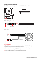
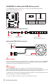
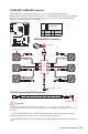
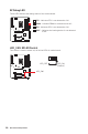
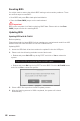
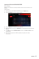
Table Of Contents
- Quick Start
- Specifications
- Package contents
- Block Diagram
- Rear I/O Panel
- Overview of Components
- CPU Socket
- DIMM Slots
- PCI_E1~5: PCIe Expansion Slots
- M2_1~2: M.2 Slots (Key M)
- SATA1~6: SATA 6Gb/s Connectors
- JFP1, JFP2: Front Panel Connectors
- JAUD1: Front Audio Connector
- CPU_PWR1~2, ATX_PWR1: Power Connectors
- JUSBC1: USB 3.2 Gen 2 10Gbps Type-C Connector
- JUSB3: USB 3.2 Gen 1 5Gbps Connector
- JUSB1~2: USB 2.0 Connectors
- JTPM1: TPM Module Connector
- CPU_FAN1, PUMP_FAN1, SYS_FAN1~6: Fan Connectors
- JCI1: Chassis Intrusion Connector
- JCOM1: Serial Port Connector
- JBAT1: Clear CMOS (Reset BIOS) Jumper
- JTBT1: Thunderbolt Add-on Card Connector
- JRTD3: Intel RTD3 Connector
- JRGB1: RGB LED connector
- JRAINBOW1~2: Addressable RGB LED connectors
- JCORSAIR1: CORSAIR Connector
- EZ Debug LED
- LED_SW1: EZ LED Control
- Installing OS, Drivers & Utilities
- UEFI BIOS
- RAID Configuration
- Intel® Optane™ Memory Configuration
- Troubleshooting
- CPU_FAN1, PUMP_FAN1, SYS_FAN1~6: Fan Connectors
- CPU_PWR1~2, ATX_PWR1: Power Connectors
- CPU Socket
- DIMM Slots
- JAUD1: Front Audio Connector
- JBAT1: Clear CMOS (Reset BIOS) Jumper
- JCI1: Chassis Intrusion Connector
- JCOM1: Serial Port Connector
- JCORSAIR1: CORSAIR Connector
- JFP1, JFP2: Front Panel Connectors
- JRAINBOW1~2: Addressable RGB LED connectors
- JRGB1: RGB LED connector
- JRTD3: Intel RTD3 Connector
- JTBT1: Thunderbolt Add-on Card Connector
- JTPM1: TPM Module Connector
- JUSB1~2: USB 2.0 Connectors
- JUSB3: USB 3.2 Gen1 Connector
- JUSBC1: USB 3.2 Gen 2 Type-C Connector
- LED_SW1: EZ LED Control
- M2_1~2: M.2 Slots (Key M)
- PCI_E1~5: PCIe Expansion Slots
- SATA1~6: SATA 6Gb/s Connectors
50
UEFI BIOS
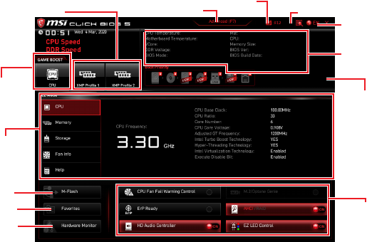
EZ Mode
At EZ mode, it provides the basic system information and allows you to configure the
basic setting. To configure the advanced BIOS settings, please enter the Advanced
Mode by pressing the Setup Mode switch or F7 function key.
XMP Profile
Component
Information
System
information
Boot device
priority bar
Function
buttons
Language
GAME BOOST
Search
Screenshot
Setup Mode switch
M-Flash
Hardware
Monitor
Favorites
∙ GAME BOOST - click on it to toggle the GAME BOOST for overclocking. This function
is only available when both of the motherboard and CPU are supporting this function.
⚠
Important
Please don’t make any changes in OC menu and don’t load defaults to keep the
optimal performance and system stability after activating the GAME BOOST function.
∙ XMP Profile - allows you to select the XMP profile for memory to overclock. This
function is only available when the system, memory and CPU are supporting this
function.
∙ Setup Mode switch - press this tab or the F7 key to switch between Advanced mode
and EZ mode.
∙ Screenshot - click on this tab or the F12 key to take a screenshot and save it to USB
flash drive (FAT/ FAT32 format only).
∙ Search - click on this tab or the Ctrl+F keys to enter the search page. It allows you
to search by BIOS item name. Move the mouse over a blank space and right click the
mouse to exit the search page.
⚠
Important
In search page, only the F6, F10 and F12 function keys are available.