
User's Manual
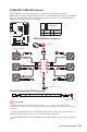
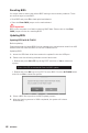
Table Of Contents
- Quick Start
- Specifications
- Package contents
- Block Diagram
- Rear I/O Panel
- Overview of Components
- CPU Socket
- DIMM Slots
- PCI_E1~5: PCIe Expansion Slots
- M2_1~2: M.2 Slots (Key M)
- SATA1~6: SATA 6Gb/s Connectors
- JFP1, JFP2: Front Panel Connectors
- JAUD1: Front Audio Connector
- CPU_PWR1~2, ATX_PWR1: Power Connectors
- JUSBC1: USB 3.2 Gen 2 10Gbps Type-C Connector
- JUSB3: USB 3.2 Gen 1 5Gbps Connector
- JUSB1~2: USB 2.0 Connectors
- JTPM1: TPM Module Connector
- CPU_FAN1, PUMP_FAN1, SYS_FAN1~6: Fan Connectors
- JCI1: Chassis Intrusion Connector
- JCOM1: Serial Port Connector
- JBAT1: Clear CMOS (Reset BIOS) Jumper
- JTBT1: Thunderbolt Add-on Card Connector
- JRTD3: Intel RTD3 Connector
- JRGB1: RGB LED connector
- JRAINBOW1~2: Addressable RGB LED connectors
- JCORSAIR1: CORSAIR Connector
- EZ Debug LED
- LED_SW1: EZ LED Control
- Installing OS, Drivers & Utilities
- UEFI BIOS
- RAID Configuration
- Intel® Optane™ Memory Configuration
- Troubleshooting
- CPU_FAN1, PUMP_FAN1, SYS_FAN1~6: Fan Connectors
- CPU_PWR1~2, ATX_PWR1: Power Connectors
- CPU Socket
- DIMM Slots
- JAUD1: Front Audio Connector
- JBAT1: Clear CMOS (Reset BIOS) Jumper
- JCI1: Chassis Intrusion Connector
- JCOM1: Serial Port Connector
- JCORSAIR1: CORSAIR Connector
- JFP1, JFP2: Front Panel Connectors
- JRAINBOW1~2: Addressable RGB LED connectors
- JRGB1: RGB LED connector
- JRTD3: Intel RTD3 Connector
- JTBT1: Thunderbolt Add-on Card Connector
- JTPM1: TPM Module Connector
- JUSB1~2: USB 2.0 Connectors
- JUSB3: USB 3.2 Gen1 Connector
- JUSBC1: USB 3.2 Gen 2 Type-C Connector
- LED_SW1: EZ LED Control
- M2_1~2: M.2 Slots (Key M)
- PCI_E1~5: PCIe Expansion Slots
- SATA1~6: SATA 6Gb/s Connectors
43
Overview of Components
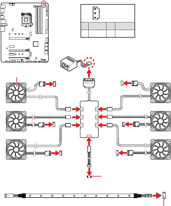
JCORSAIR1: CORSAIR Connector
The JCORSAIR1 connector allows you to connect the CORSAIR Individually
Addressable Lighting PRO RGB LED strips 5V or CORSAIR RGB fans with the CORSAIR
fan hub. Once all items are connected properly, you can control the CORSAIR RGB
LED strips and fans with MSI's software.
1
JCORSAIR1
1 +5V 2 Data
3 Ground
CORSAIR RGB Fan Connection
⚠
Important
∙
Fans must start at 1 and continue in series. 1 > 2 > 3 > 4 > 5 > 6. Any fan not
connected in series will break communication and the RGB LED lighting function will
not work.
∙
Quantity of RGB LED Fans or RGB LED Lighting PRO strips supported may differ
between models. Please refer to the motherboard specification.
∙
CORSAIR RGB LED Fan and CORSAIR Lighting Node PRO can’t be used at the same
time.
JCORSAIR1 connector
SYS_FAN
SYS_FAN
SYS_FAN
SYS_FAN
SYS_FAN
SYS_FAN
1
2
34
5
6
JCORSAIR1 connector
SATA power
CORSAIR Lighting Node PRO Connection
CORSAIR RGB LED fan
CORSAIR fan hub